Hardware Project: Refining a Multispectral Imaging System
Team
Sean McIntyre, Johannes Giorgis, Matisse Milovich, Paul Villers
Introduction
Background
Multispectral imaging uses wavelength-specific filters to capture light at certain frequencies, to gain information about the spectrum of light reflected off an object in question. Different sets of wavelength-specific filters can provide information about the spectrum not available to the human eye either by increasing the resolution of the spectrum (using many filters) or by increasing the range of the spectrum (using UV and infrared filters). Multispectral imaging has a number of different applications. Obtaining high granularity spectral information about reflected color in a painting, for example, can distinguish between two colors that are metamers to the human eye, and therefore provide information about what pigments and dyes may have been used in different geographic zones or in different time periods to create apparently similar colors.
Project Description
The goal of the project was to build a multispectral imaging system based on a rotating color filter wheel and monochrome camera. The system will be used to capture images of paintings in the Cantor Arts museum.

A high-level schematic (above) shows the multispectral imaging process; our objective is to design a system which connects the lens to the filter wheel and the filter wheel to the camera, so that transmitted light is recorded by the sensor and an image file is saved on the computer. Finally, a processing step operates on the set of spectral images before viewing and interpretation.
Issues with previous set-up
At the project outset, the components were neither physically nor electronically connected. The filter wheel housing wasn't able to connect the camera or lens, because only one side of the housing had c-mount connectivity. The stock adaptor was too thick and would have increased the lens - sensor distance which would have reduced the focal range of the lens. Furthermore, the filter wheel and camera were disconnected and had manual functionality, making it tedious to acquire a series of images.
Video of using filter wheel manually

Design Specifications
The project had two principal design components. The first objective was to build physical connections, "adaptors" between the lens-filter-camera system to ensure that all light reaching the camera had first passed through the lens and the filter. The second goal was to automate the photo-capture system via communication between a computer, an Arduino, and the camera.
Adaptors
We were asked to:
- Couple the filter wheel to the camera on one side and the lens on the other side.
- Minimize distance between lens and camera as much as possible.
As we started designing, we set additional specifications to meet:
- Ensure only the light coming through the lens reaches the camera sensor
- Design the adaptors to be easy and fast to connect
- Have threaded portions to mate with the threads on the camera, lens, and filter wheel to ensure optical axis alignment
- Withstand moment induced by the camera and lens
Automated photo-capture
- Automate the process of taking and saving eight images in a row
- Require minimal user input
Components available
- Point Grey monochromatic camera with c-mount threading, USB port, GPIO port
- Schneider Xenoplan lens
- Edmund optics bandpass (650nm, etc) filters, each with c-mount threading
- Edmund optics Intelligent Filter Wheel (IFW) with control box and housing
- Arduino Mega 2560 Board
- PC with FlyCap software and SDK
Methods
System Overview
The system schematic below shows connection of the computer, Arduino, Filter Wheel, Camera and Lens via communication paths in red and physical components in purple.

Hardware Design
The design process involved defining adaptors in terms of desired dimensions, as well as minimizing size (and therefore manufacturing cost); with the desired performance. This 3D design software “Solidworks” was used to define dimensions and tolerances properly, simulate assembly between components, and generate reliable models to 3D print.
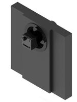
Camera - Wheel Adaptor
The proposed adaptor is shown below:
- Camera - Wheel Adaptor
-

-


In order to minimize the distance between the camera and the filters, the adaptor was designed in such way that the camera would be held inside it and, at the same time, light would be blocked from any other part.
The dimension is such that the adaptor can be easily inserted inside the filter wheel and held with allen hex keys; and the lid was designed to block light from the outside. The threading is such that it will accept traditional C-Mount Female Couplers of 1 in., which corresponds to the camera. The mechanical specs are here.
Lens - Wheel Adaptor
The proposed adaptor is shown below:
- Lens - Wheel Adaptor
-

-


This adaptor was designed with both internal and external threading. The inner thread allows the component to receive traditional male C mounts couplers, which is the standard coupling between many optical components like lens. The outer threading is a traditional UNC thread which couples exactly with the one the filter wheel has. The flange to prevent light from entering was also added. The mechanical specs are here.
Manufacturing Considerations Both designs succeed in meeting all of our specs. Due to the complication of standard manufacturing, 3D printing was employed. Since the threads are so small, the chosen printing equipment was the Projet 3500, using the ultra high printing format.
Electrical/Software Design
Arduino
The goal of the Arduino control phase was to design a communication system that would accept inputs from the camera at the start of the picture capture sequence, then adjust the filter wheel accordingly, and signal the capture of the remaining set of pictures through appropriate filters with input/output communication with the camera. The impetus behind using the Arduino as an interface between the camera and filter wheel was a desire to automate the capture and filter wheel movement cycle, which was previously done manually with physical buttons on the filter wheel control box.
The design process involved defining clear states that the Arduino would enter and exit based on signals sent to and received from the camera and sent to the filter wheel. We decided the camera’s states should be (1) waiting for an initial signal from the camera indicating that the camera was initialized and ready to begin the image capture sequence, (2) waiting for the filter wheel to finish turning, and (3) waiting for a ‘picture taken’ signal from the camera. As described in the flowchart below, the Arduino cycles between states according to the following inputs and outputs.

This system allows the Arduino to run autonomously, because, after an initialization signal from the camera, the filter wheel initialize, then capture images and increment filter until an image from every filter was captured, at which point the system would return to the waiting for an initial signal state, ready for the next sequence of images. Since the only user command for a given acquisition sequence is to initialize the camera, the Arduino runs without further user input.
One important design decision was the communication protocol between the Arduino and the filter wheel. While the filter wheel did offer a serial communication option, we found a much more efficient method was to use a preinstalled protocol (called SBIG for Santa Barbara Instruments Group) which changes filter wheel position according to digital input pulse duration, i.e. encoding filter number with pulse duration. The SBIG protocol on the filter wheel is an input-only protocol, so we measured duration of the image capture and filter wheel incrementation process to ensure the Arduino would delay further operations until that process was complete.
Camera Image Acquisition
The automatic image acquisition program was created from two different sample programs. Both programs came with the FlyCapture2 SDK. They can be found under the ‘src’ folder of the installed folder.
The first program is FlyCaptureTest. This program reports the connected camera’s information, captures a series of images from it, records the amount of time taken to grab these images, and saves the last image into the current directory. The second program is AsyncTriggerEx. This program demonstrates a few of the basic asynchronous trigger capabilities of compatible cameras. The asynchronous trigger choices are either an external hardware trigger or via the camera’s internal software trigger. The program captures a specified number of images before exiting. Code from FlyCaptureTest was put into AsyncTriggerEx to create our Automatic Image Acquisition program. The program had the following use case:
  	Usage: Multispectrald.exe numImages name format
       Options:
               numImages	Enter number of desired pictures to take
               name     	Specify a name for the batch of pictures
               format    	Insert a format for pictures (pgm, jpeg, tiff)
  	        Example: \bin> Multispectrald.exe 8 test0 jpeg
The example use case above requests the program to take 8 pictures with the base name, test01 (test011, test012..etc) in jpeg format. The program had the following logic flow:

Connection Phase: In this phase, the program detects the number of connected cameras. If there are none, the program exits. Otherwise, it proceeds to connect to the camera and powers it on. After it waits for the camera to complete power-up, it gets the camera’s information.
Initialization Phase: In this phase, the program initializes the camera and it’s settings. It first checks the arguments passed by the user in the command line. If there are insufficient arguments, it prints the use case of the program (shown above). Otherwise it stores the arguments (number of images, name and format). At this stage, a SOFTWARE_TRIGGER_CAMERA variable was defined. This was used for development purposes to allow independent debugging of the program without the need for an external trigger to be connected. It gets the current trigger, before setting it to mode 0, the standard external trigger. The camera starts integrating incoming light from external trigger input falling/rising edge. In the diagram below, the exposure time describes the integration time:

It gets the current strobe settings, before setting it to GPIO Mode 3. This mode outputs a voltage pin of fixed delay, relative either to the start of integration or to the time of an asynchronous trigger. The previous is the default setting. When in this mode, a GPIO pin can be configured to output a variable strobe pattern. The trigger source is set (software or external). It polls the camera to ensure it is ready, gets and sets its configuration. It also sends the Arduino a 'Send Filter Wheel to Home' command via a software trigger. This starts the next phase, image acquisition.
Image Acquisition Phase: In this phase, the program starts capturing images after having checked the camera is ready to do so at the end of the previous phase. The trigger source is checked before it enters a for-loop (number of images specified sets the number of loops). Another development related software trigger check is performed. It proceeds to grab the image, convert it to a raw image, creates a unique filename before saving the image into the current directory. The current directory is where the executable file is. As each picture is taken and saved, it prints to console a “Picture number saved” message to the console.
At the end, the trigger mode and strobe are set to off, it stops capturing images and disconnects from the camera.
Results
Hardware Results
The final proposed assembly is:
- Proposed Final Assembly
-
-


An image of the final assembly is shown below.


Our adaptors met all specifications and surpassed our expectations. With only two iterations of 3D-printed parts, we produced two pieces that securely mounted to the filter wheel and held the camera and lens respectively. Using 3D printing was a relatively fast process compared to machining by hand, but was a gamble. The C-Mount threads had to be designed from scratch in SolidWorks with limited tolerance information. We adjusted the thread profile between the first and second iteration to improve mating with the lens and camera. At 32 threads-per-inch, we were concerned that the resolution of the 3D printer and the strength of the printed material (ABS plastic) would not suffice. Happily, the printing resolution and our design of the thread profile works well for comfortable and secure threading.

- Our adaptors support the weight and moment induced by the lens and camera.

- Because our design used concentric circles and a threaded mount, we ensured that the camera sensor, filter, and lens shared a common axis.

- Compared to the off-the-shelf adaptor available from Optec, the filter wheel manufacturer, our adaptors reduce the distance from camera to filter wheel by approximately 40%. There was no previous adaptor from the lens to the filter wheel. Our design brings the lens as close as possible without risking damage to the lens from the rotating filter wheel.

This is basically, the minimum distance we can achieve using the current camera and filter wheel (1mm). We got a percentage decrease in distance of almost 40% with the improved adaptors.


Electrical/Software Results
The final circuit, with the filter wheel and camera connected via breadboard to the Arduino, is shown below.

The software has very simple functionality, which satisfies the goal of one-click implementation. The user runs an executable file on the PC, which triggers the camera to initialize, which in turn sends an initialization trigger to the Arduino, pre-loaded with the necessary code for communicating between the filter wheel and camera. Once the Arduino triggers the filter wheel to go to its first position, the image acquisition sequence progresses, saving the files on the PC, until all 8 images have been taken. The Arduino is now ready for the next initialization trigger from the camera, which will occur next time the executable file is run.
A video of the system is here: Demonstration of automated system. Though it is not shown in the video, it is possible to run the system with one line of input in the command line.

Image Results
The Edmond Optics bandpass filters used to capture images had ~50nm wide transmission peaks at 450nm, 500nm, 600nm, 650nm, 700nm, 800nm and 900nm. Below are images captured with filters of different regions of the Macbeth color checker. The color image of the portion of the checker (top left) is followed by the images taken with each of the seven filters in the order listed, from top left to bottom right.
- Macbeth Blue Patch
-

-

-

-

-

-

-

-


- Macbeth Green Patch
-

-

-

-

-

-

-

-


- Macbeth Yellow Patch
-

-

-

-

-

-

-

-


Conclusions
Summary
We met the objective of the project and delivered an improved system in terms of successful mating between physical components and a working automated photo capture system. For the purpose of taking images of full art pieces, the distance between camera sensor and lens is still too large. Our proposed solution to this problem is to use a different camera-lens pair that is meant to have a larger distance between the lens and sensor.
Engineering Challenges
The most challenging and time-consuming portions of the project were as follows:
- Designing the C-Mount threads from scratch with limited information about the thread profile. We carefully researched C-Mount thread specifications and designed within the stated tolerances. Nevertheless, after testing our first iteration of 3D printed parts we needed to fine-tune the thread profile to reduce friction with the lens and camera threads.
- Several full days were spent trying to use the SDK files from Point Grey. We finally found that the files require a highly specific compiler and library set. The user manual gives very little information.
- We were unable to establish serial communication with the filter wheel, possibly because of the version of filter wheel we have. If it is possible, it is certainly not as easy as it is made out to be in the documentation. We worked around this issue by using the filter wheel’s other communication protocol, the “Santa Barbara” protocol, which uses pulses of varying widths to set filter positions. This communication system is one-way; it does not allow us to receive signals from the filter wheel. To compensate, we used timed delays of appropriate length to coordinate the camera with the filter wheel.
- The communication and timing between the filter wheel and camera has been an ongoing challenge. The more the system is automated, the more it depends on all connections working seamlessly. The most critical step is the correct initialization of the camera. Full understanding of the camera system is not possible from its technical reference document, but requires contacting the manufacturer.
Next Steps
With more time we would calibrate the system using a Macbeth ColorChecker and obtain the light intensity per waveband. Our system may be used in the near future to capture data from artwork at Stanford’s Cantor Arts Museum, as well as from fluorescent scenes.
References
An LED-based lighting system for acquiring multispectral scenes - Parmar et. al.
Multispectral Imaging Using Multiplexed Illumination - Park et. al.
Multispectral Filter Wheel Cameras: Geometric Distortion Model and Compensation Algorithms - Brauers et. al.
Appendix I - Code and Data
Appendix II - Work Partition
- Design and finalization of 3D printed adapters - Matisse and Paul
- Design and implementation of Arduino control - Sean and Matisse
- Finalization of circuit - Sean
- C++ program to calibrate camera and save images - Paul and Johnny
- Testing of entire system - All
We would like to thank Henryk for pushing us to make the system as automated as possible, for guidance, and for use of his lab space.