KorczynskiMcCall
Back to Psych 221 Projects 2013
Active LED Illumination: Wireless Communication
- Active LED Illumination: Wireless Control
-
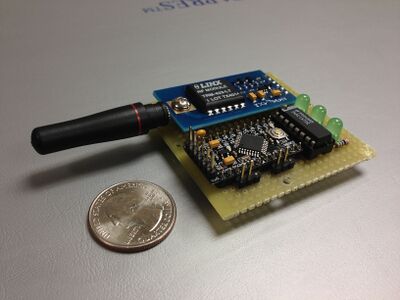 Figure 1. Transmitter
 -
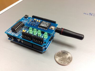 Figure 2. Receiver


Background

This project idea coincides with several other class projects with regards to experimenting with Active LED Illumination (See References below). Specifically, these experiments involve illuminating objects with high intensity LEDs ( at various levels) to observe and analyze its spectral distribution at high frame rates and various shutter times.
For this project, as further described below, we expect the user to interface our system with the FL3- U3 camera (Shown in Figure 3). We used this camera as a guideline to understand the programming functionality and capability to capture these high frame rate images. This camera acts as a host device that will be programmed to send configuration data (LED module ID # and intensity values) to various LED modules around a room as well as the actual LED Strobe signal to control high density light for high frequencies (in micro-time).
Design Specifications
- Enable multiple programmable light sources for experiments

- Synchronous wireless trigger that can handle 500fps speeds

System Overview
Paragraph describing our system, how it works.....
Design
Transmitter

Receiver

Components and Cost (Bill of Materials)
Transmitter

- Arduino Pro Mini - $9.95 [product]
- Parallax Transceiver - $39.95 [product] [datasheet]
- 74AC157 Multiplexer - $0.15 [product] [datasheet]
- 3 56Ω resistors
- 2 3-pin headers (0.1" spacing)
- 3 Green LEDS - [datasheet]
- Perfboard - $5.95 [product]
Total Transmitter Cost: $56
Receiver

- Arduino Uno (or cheaper alternative)- $29.95 [product]
- Parallax Transceiver - $39.95 [product] [datasheet]
- 74HC138 Demultiplexer - $0.35 [product] [datasheet]
- 4 150Ω resistors
- 1 3-pin header (0.1" spacing)
- 4 Green LEDS - [datasheet]
- ArduinoShield - $4.95 [product]
Total Reciever Cost: $75 (or $56 with cheaper Arduino)
Design Methods and Execution
Project Exploration
Looking at Xbees
Communication Protocol Definition with Arduino
Creation of custom data packets How do they interact with one another
Transmitter
sends configuration data 5 times (provides margin for error), then switches to LED trigger mode
Receiver
Software Error Correction
CRC checking
Prototype and Assembly
Testing and Camera Emulator
Results
Achieved Specifications
We were able to confirm: distance and delay (synchronization timing)
Tradeoffs
Speed vs Error: Ex. with Xbees
Conclusions
Here is where you say what your results mean.
References - Resources and related work
- PSYCH W13 hardware groups: [Active-LED Based Illumination (Super Cap Flash System)], [Active LED Based Illumination Control]
- Jameco Electronics Catalog ([1])
- The Importance of Flash Sync Speed [2].
Appendix I - Code
Code
Transmitter: Transmitter code for Arduino
Receiver: Receiver code for Arduino
Camera_Emulator: Camera Emulator
Appendix II - Work partition
Design Planning/Schematics: Allison and Corey
Wireless Transmitter Xbee Testing: Allison and Corey
Final Component Selection: Corey
Firmware and Testing software: Corey
Soldering/Assembly: Allison
Presentation and Wiki: Allison