KorczynskiMcCall
Back to Psych 221 Projects 2013
Active LED Illumination: Wireless Communication
- Active LED Illumination: Wireless Control
-
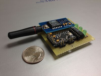 Figure 1. Transmitter
 -
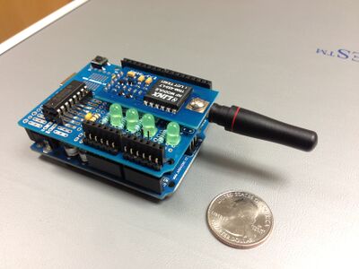 Figure 2. Receiver


Background

This project idea coincides with several other class projects with regards to experimenting with Active LED Illumination (See References below). Specifically, these experiments involve illuminating objects with high intensity LEDs ( at various levels) to observe and analyze its spectral distribution at high frame rates and various shutter times.
For this project, as further described below, we expect the user to interface our system with the FL3- U3 camera (Shown in Figure 3). We used this camera as a guideline to understand the programming functionality and capability to capture these high frame rate images. This camera acts as a host device that will be programmed to send configuration data (LED module ID # and intensity values) to various LED modules around a room as well as the actual LED Strobe signal to control high density light for high frequencies (in micro-time).
Design Specifications
Our end goal in this project is centered around the following two tasks:
- Enable multiple programmable light sources for experiments like the one shown below, where mutliple LED modules light up a room for an object and are controlled by one single host device.

- Create a synchronous wireless trigger that can handle 500fps (frames per second) speeds. With this design specification, we are expecting the ability to trigger and simultaneously light an LED every 4ms for a specific amount of integration time. Looking at Figure 5, the rising edge of the square wave should simultaneously start both the shutter and LED, then, the LED and shutter remain on for some desired time before ending the shutter and LED flash with the falling edge.


For this task, its important to understand the process for how a camera takes a picture with flash lighting (i.e. an LED strobe signal), as shown above in Figure 5. Specifically, the LED flash when timed correctly, can add a lot of balance to the lighting for a photo; however, is the LED flash is out of sync with the camera shutter, then the image ends up being blacked out and disrupted. To verify that the flash appropriately complements the image being captured , it is crucial that the camera timing for the strobe and shutter time line up with the flash LED signal being output. This characteristic is called the synchronization speed; timing plays a very large role in this project because we are trying to obtain images from really high frame rates. The goal is to achieve a 500 frames per second image capture scheme. Since timing is crucial, its important to understand what causes any delay when a signal travels from one end to the other; adding wireless communication on top of that (where signals have to be processed) causes concern for adding unwanted delay. Many cameras today are limited to only that synchronization speeds of the camera Many cameras today are limited to only 1/250 synchronization speeds.
System Overview
Our approach to creating this synchronous wireless interface (from a single camera to multiple LED modules) is to provide simple interfacing between the wireless transmitter and receivers. Specifically, our approach is to transfer both the configuration data as well as the LED strobe over one RF channel. With this simplistic interface, we had to intelligently design a scheme for distinguishing the two modes from one another. In each experiment, we expect the camera to first program and configure the specific LED modules and their desired intensity levels. After that setup, the transmitter and receiver move into a new mode which pertains to just the transmission of the trigger signal to flash the LEDs synchronously with the camera shutter. The sections below go into further detail to help explain how the individual components send and receive this camera data.
Design
Transmitter
-
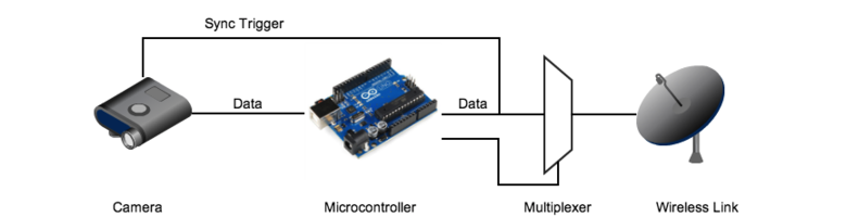 Figure 7: Block Diagram of Transmitter

The above block diagram provides a high level understanding of the transmitter and describes how this board is able to send both the configuration data and LED trigger over the same RF line. The camera will send its configuration data into an Arduino for pre-tranmission processing. The Arduino then serves as a traffic controller to process the configuration requests and to control a multiplexer that pciks which signal to send (the trigger signal or the configuration data) of RF to the receiver.
Receiver
-
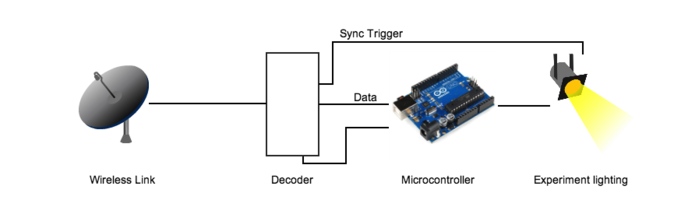 Figure 7: Block Diagram of Receiver

The above block diagram provides a high level overview of the receiver circuit used for this wireless communication. Its architecture is very similar to that of the transmitter, only in reverse order. The RF transmitter is now receiver and will take in a RF signal and pass it through a decoder through Arduino control. The controls of the Arduino are led by the sequential flow of the input signal; it first expects configuration data, then it expects the trigger/LED strobe. More details of the logistics of the specific algorithm will be explained later on this page.
Components and Cost (Bill of Materials)
Transmitter

- Arduino Pro Mini - $9.95 [product]
- Parallax Transceiver - $39.95 [product] [datasheet]
- 74AC157 Multiplexer - $0.15 [product] [datasheet]
- 3 56Ω resistors
- 2 3-pin headers (0.1" spacing)
- 3 Green LEDS - [datasheet]
- Perfboard - $5.95 [product]
Total Transmitter Cost: $56
Receiver

- Arduino Uno (or cheaper alternative)- $29.95 [product]
- Parallax Transceiver - $39.95 [product] [datasheet]
- 74HC138 Demultiplexer - $0.35 [product] [datasheet]
- 4 150Ω resistors
- 1 3-pin header (0.1" spacing)
- 4 Green LEDS - [datasheet]
- ArduinoShield - $4.95 [product]
Total Reciever Cost: $75 (or $56 with cheaper Arduino)
Design Methods and Execution
Project Exploration
- We began this project with some research and meetings with Henryk to discuss the design specifications of this project and clarify our goals. Our original plan was to be very simplistic and use Xbee Transceivers with the Arduino to easily sync the LED flash with the camera shutter, but later testing led us to a use a different solution (more details to follow). In addition to choosing the wireless protocol, we collectively determined the type of Arduino microcontrollers to use for this project in terms of input/output pins and decided to power our system off 3.3V (due to the Xbee power). We also looked into the different techniques for transmitting the trigger signal and the UART configuration data (i.e. sending both trigger and configuration data and send both over UART in a special data packet or enabling I/O line passing for the trigger signal and simultaneoulsy using the UART interface the configuration data.
- When programming the Xbees, we noticed that we were not able to achieve our desired synchronization speed of <<2ms to allow for 500 frames per second rates, so we had to find a solution that could handle faster delay time and faster transmission rates. We ended up choosing the Parallax 433MHz RF board that utilized the LinxLT chip. data sheet With this chip, we were able to achieve much faster transmission rates and less delay time. With this design choice, we had to create our own communication protocol for information transfer between the camera and the LEDs.
Communication Protocol Definition with Arduino
As mentioned above, we chose to use the Parallax LinxLT RF Transceiver for our final wireless communication interface. With this design choice, the issue about how to switch between sending configuration settings and the trigger signal was still apparent. So, we decided to use a multiplexer (mux) on the transmitter and a de-multiplexer (decoder) on the receiver. Based on a sequential state machine, the Arduino had control logic inside to make decisions about what to send over RF. Also, the Arduino was responsible for handling the configuration data that came from the camera. So, we set up our own transmission protocol and data packet format to send over to the LEDs the configuration information. This data packet format is shown below in Figure blah. Most of this data packet is built from the same format of information that the camera sends to the Arduino. First, we send a start bit, then an LED ID # that would tell which wireless LED receiver would be getting the correct configuration settings. After the LED module ID, we receive a number N to represent the length of the packet of configured intensity values. Following that, we have N number of values (V0,V1,V2,....Vn) that represent the specific intensity values for each LED within the module. Finally, we have a stop bit. The packet format I just mentioned is something that comes directly from the Camera serial interface. However, there was one more thing we needed to add.
- We all noticed that (due to the really fast speeds of the transmission) there could exist a higher probability of error than the error the slower Xbee protocol. So, we decided to add in our own error detection checker.

Software Error Detection
As mentioned above, the configuration information and data packet thats sent to the LED modules is mostly the same from its original form from the camera. However, we must account of error (from the high speed transmission), so we added our own form of error detection using a technique called CRC.
- [Cyclic Redundancy Checking] is an error detection scheme where blocks of data entering these systems get a short check value attached, based on the remainder of a polynomial division of their contents. Once the data packet is received, another calculation and comparison of a check value is done to find out if there was any bit corruption over than data transmission. This technique does not fix the errors, but it does make it known that some error(s) did occur over the transmission.
Transmitter
Sequential Behavior:
- Reads in Command from Camera
- If command 0x53 is said, Enter Config Mode and set up configuration data packets
- Transfer Camera's data packet to own buffer and then add CRC.
- Transmit Packet 5 times (to allow for CRC correction) aka redundancy
- Reads in Command from Camera to switch to Trigger Mode
- Alerts Receiver to get into Trigger mode
- Transmit trigger
- Return to Configuration mode (Step 2.)
Receiver
Sequential Behavior:
- Check and decipher incoming radio signal for configuration of LEDs
- Check CRC
- Configure LED hardware
- Switch to Trigger mode
- Trigger to LED Modules
- Feed back to next loop
- Check Signal Strength
- Repeat
Prototype and Assembly
Transmitter Schematic and Assembly
- Transmitter Hardware
-
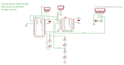 Figure 9a: Transmitter Schematic
 -
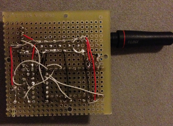 Figure 9b: Soldering TX


Receiver Schematic and Assembly
- Receiver Hardware
-
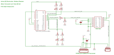 Figure 10a: Receiver Schematic
 -
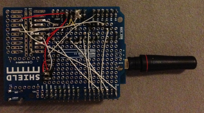 Figure 10b: Soldering RX


Testing and Camera Emulator
In the beginning of our functionality testing, we started by sending trigger signals from the Transmitter Arduino to the Receiver Arduino and measured the delay between the two signals. With the Xbees, we measured at best a 4ms delay, but when we hooked up this new board and chip Parallax and LinxLT. It was really fascinating to measure a delay almost a 1/100x reduction just from choosing a different receiver. In addition to delay, we also cared about the distance between transmitter and receiver and tried to test and understand if there would be any extra delay from the longer distance in between. The picture below shows our setup of this particular test.

As part of our testing, we ended up using an Arduino Fio to help emulate the hardware of the camera. With this set up, we could actually test our transmitter and receiver circuits as a whole. For this camera emulator, we generated a square wave to resemble the LED strobe/trigger. We also started writing/sending fake data packets to verify that the transmitter and receiver understand what to do into next.
Results
The following section describes our final observations, results, and the lessons learned throughout this project.
Achieved Specifications

We were able to confirm a few specifics related to our design goals in terms of:
- Distance: Able to measure 250ft of distance without a disturbance or additional delay in the received signal. This specification was derived from the testing mentioned in the previous section.
- Delay (synchronization timing): We were able to measure ~40µs of delay between the Transmitter and Receiver Trigger signals. This delay is most likely based on propagation delays going through the multiplexer on the transmitter and then the propagation delays through the decoder in the receiver.
Overall, we were able to prove that this system can handle the data transmission and synchronization timing that we originally designed for. In particular, the above oscilloscope picture shows that this design can handle speeds up to 22,000-25000Hz. The picture below shows a 250Hz, which could emulate a camera running at 250 fps. There is a 100x oversampling margin between those two frequencies and a 50x oversampling margin for a 500 fps environment.

Tradeoffs
As mentioned earlier, the Xbee transceivers we originally used ended up significantly limiting our frames per second capability. However, the Xbee wireless interface was really easy to configure, learn, and required no extra error detection/correction. When we switched to the Parallax LinxLT, the delay speeds significantly improved and we were able to run at a shutter speed of 500 fps and achieve our design goal, but the errors were more likely to occur. Our methods to detect these errors is fairly simplistic in concept, but it has worked really well.
Conclusions
We were very excited to take on this project and get to understand the technology that goes into a camera interface. Although our project was more geared towards wireless communication, we gained a lot of perspective about the details of light synchronization and its importance when trying to capture a light balanced image from a high speed camera. One significant accomplishment for us was finding a low cost solution to accomplish the 500fps shutter speed. When we started researching for this project and looking for design ideas, we noticed that typical camera wireless transmitters and receivers for LED strobes were well over $100 or even $350. It was exciting to build a prototype and I look forward to seeing all the hardware group projects combine and turn into something that can be useful for experiments.
References - Resources and related work
- PSYCH W13 hardware groups: [Active-LED Based Illumination (Super Cap Flash System)], [Active LED Based Illumination Control]
- Jameco Electronics Catalog ([[1]])
- The Importance of Flash Sync Speed [[2]].
- [Cyclic Redundancy Check]
Appendix I - Code
Code
Transmitter: Transmitter Code for Arduino
Receiver: Receiver Code for Arduino
Camera_Emulator: Camera Emulator Code for Arduino
Appendix II - Work partition
The following list describes our individual efforts and focus for the different parts of the project. Even though we sometimes had focused roles, we were always very collaborative with each other for the whole duration of this project.
- Design Planning/Schematics: Allison and Corey
- Wireless Transmitter Xbee Testing: Allison and Corey
- Final Component Selection: Corey
- Firmware and Testing software: Corey
- Soldering/Assembly: Allison
- Presentation and Wiki: Allison