2009 WinawerDoughertyWandell
Back to Psych 204 Projects 2009
Project Title - Retinotopic maps in MNI space
Your project overview goes here. For example: Much of the visual cortex is organized into visual field maps: nearby neurons have receptive fields at nearby locations in the image. These maps are usually identified in individual subjects. The precise location of each map may be different in different brains. For this project, we asked how the quality of the maps would compare using (a) standard retinoptic methods on individual brains or (b) group-averaged brains projected into MNI space.
Note that this is a project template. Other styles are possible. For example, you could use a multiple page format.
Background
Retinotopic maps
You can use subsections if you like.
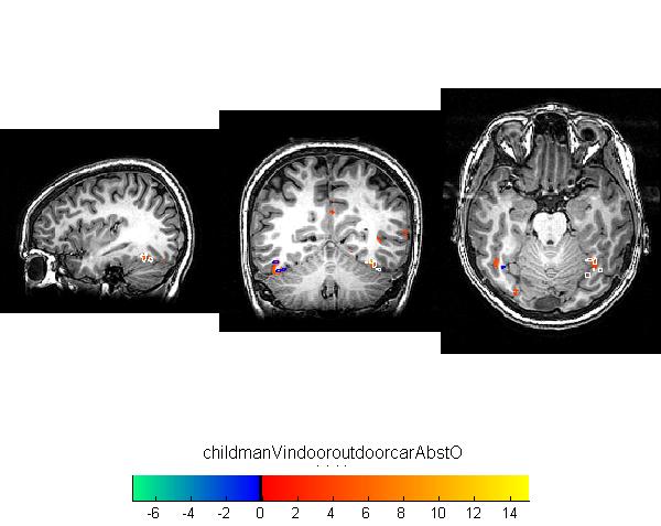
Below is an example of a retinotopic map. Or, to be precise, below will be an example of a retinotopic map once the image is uploaded. To add an image, simply put text like this inside double brackets 'MyFile.jpg | My figure caption'. When you save this text and click on the link, the wiki will ask you for the figure.

Below is another example of a reinotopic map in a different subject.
Figure 2
Once you upload the images, they look like this. Note that you can control many features of the images, like whether to show a thumbnail, and the display resolution.

MNI space
MNI is an abbreviation for Montreal Neurological Institute.
Methods
Measuring retinotopic maps
Retinotopic maps were obtained in 5 subjects using Population Receptive Field mapping methods Dumoulin and Wandell (2008). These data were collected for another research project in the Wandell lab. We re-analyzed the data for this project, as described below.
Subjects
Subjects were 5 healthy volunteers.
MR acquisition
Data were obtained on a GE scanner. Et cetera.
MR Analysis
The MR data was analyzed using mrVista software tools.
Pre-processing
All data were slice-time corrected, motion corrected, and repeated scans were averaged together to create a single average scan for each subject. Et cetera.
PRF model fits
PRF models were fit with a 2-gaussian model.
MNI space
After a pRF model was solved for each subject, the model was trasnformed into MNI template space. This was done by first aligning the high resolution t1-weighted anatomical scan from each subject to an MNI template. Since the pRF model was coregistered to the t1-anatomical scan, the same alignment matrix could then be applied to the pRF model.
Once each pRF model was aligned to MNI space, 4 model parameters - x, y, sigma, and r^2 - were averaged across each of the 6 subjects in each voxel.
Et cetera.
Results - What you found
Retinotopic models in native space
Some text. Some analysis. Some figures.
Retinotopic models in individual subjects transformed into MNI space
Some text. Some analysis. Some figures.
Retinotopic models in group-averaged data on the MNI template brain
Some text. Some analysis. Some figures.
Retinotopic models in group-averaged data projected back into native space
Some text. Some analysis. Some figures.
Conclusions
Here is where you say what your results mean.
References
Software
Appendix I - Code and Data
Code
Data
Equations
If you want to use equations, you can use the same formats that are use on wikipidea. This example of equation use is copied and pasted from wikipedia's article on the DFT.
The sequence of N complex numbers x0, ..., xN−1 is transformed into the sequence of N complex numbers X0, ..., XN−1 by the DFT according to the formula:
where i is the imaginary unit and is a primitive N'th root of unity. (This expression can also be written in terms of a DFT matrix; when scaled appropriately it becomes a unitary matrix and the Xk can thus be viewed as coefficients of x in an orthonormal basis.)
The transform is sometimes denoted by the symbol , as in or or .
The inverse discrete Fourier transform (IDFT) is given by
Appendix II - Work partition (if a group project)
Brian and Bob gave the lectures. Jon mucked around on the wiki.


