ChepkwonyChatterjee
LED Flicker system design
Application Background
Human vision science has been generally defined based on the presence of four types of photopigments in the retina: rods and three types of cones. Rods are responsible for peripheral vision under scotopic and mesopic lighting conditions. Rods are generally not associated with color vision. The cones on the other hand are present in the foveal region and are responsible for color vision under photopic conditions. The L,M,S cones are sensitive to different wavelength ranges of light.
There has been a recent discovery (This paper talks about it) of another type of non-rod non-cone photopigment in the human retina, and this is melanopsin present in the specialized ganglion cells of the retina. Melanopsin in the retina has been studied to the extent that its primary function has been determined to be signaling changes in ambient light levels to the brain throughout the day for unconscious visual reflexes, such as pupillary constriction, and regulating a number of daily behavioral and physiological rhythms, collectively called circadian rhythms. It has been suspected that Melanopsin may play some role in the human visual system as well. The role of melanopsin in color vision and temporally varying light intensity patterns is an emerging research area.
To understand the role of Melanopsin in the human visual system, researchers need a setup for conducting psychophysical experiments. The goal of our project was to build such a device which makes it easy to carry out such experiments.
High Level Device Specifications
- Should be capable of producing 4 or more primary colors.
- To test the theory that four color sensitive photopigments (L,M,S cones and melanopsin) contribute to color vision
- The flicker rate of each primary color should be programmable.
- To test the response of varying temporal frequencies of light flicker.
- The light intensity levels should be adjustable
- To allow for variation of lighting conditions to stimulate the photopigments to different levels.
- Should be an easy to use compact portable design.
- The ideal design would be that of a black box with commands for input and a optical fiber which brings the light output. The hope is to integrate this device into an fMRI testing environment.
Device Overview
The LED Flicker device is a 14-channel LED oscillator for visual experiments. It has 12-bits of color precision per channel and a refresh rate of about 2000 Hz. Each channel's programmable flicker waveform is produced by the Arduino Mega 2560 microcontroller. This device uses pulse width modulation (PWM) to achieve nearly linear intensity modulation over its entire 12-bit range. It also has a user-configurable gamma correction table for each channel to allow fine-tuning of intensity linearity. The PWM frequency is about 2KHz and it operates in phase and frequency correct mode.
User instructions
The Arduino Mega board is quite easy to use. It plugs directly into the USB port of a computer and the software for the Arduino Environment can be found here. To get started with running the LED Flicker Firmware, visit [the GIT repository for the firmware]. The files that are necessary to run the program are represented by the following Hierarchy: sketchbook (dir)
 ledFlicker       (dir)
   ledFlicker.pde
 libraries        (dir)
   Flash          (dir)
     Flash.cpp
     Flash.h
   Messenger      (dir)
     Messenger.cpp
     Messenger.h
Once the Arduino board is plugged into the USB port it should show up as a serial device (on Linux). For Windows or MAC drivers might need to be installed (follow the Arduino documentation).
If the Arduino board already has the firmware loaded on it, then it can be directly used by issuing commands from the serial interface. All commands must be enclosed by square brackets []. Type [?] at the serial interface for help on the available commands.
If the Arduino Board must be loaded with the firmware, then one must open up the Arduino application program, and navigate the files to open the ledFlicker.pde file. Then there is a (->) button on the Arduino programming editor that is used to load the design into the Aruduino board. It is important to note that the Library files must be present otherwise there will be compilation errors. Once the design is loaded, the user should open the serial interface and start sending commands.
Design
Components
- LED Array of primary lights
- For the final design : 7-in-1 round assembly LED Array
- Polymer Optics 7 LED Cell Cluster Concentrator lens arrangement
- Shown in this page Lens Optics
- Arduino Mega 2560 microcontroller Arduino website
- A circular flat top Heat Sink Diameter ~ 2 1/4th inches [ http://white.stanford.edu/teach/index.php/File:Heat_sink.jpg Heat sink picture]
- A perforated circuit board (for the intermediate design) and a breadboard (for making a prototype)
- Final design is on a PCB.
- Circuit components
- N channel MOSFETs like the 50N06L Datasheet or similar.
- npn BJTs like the 2N3904 Datasheet or similar
- 1.2 Ohm 0.5 Watt power resistors feedback resistances
- 1.82 KOhm resistances to connect the PWM signals from the Arduino to the circuit.
- Power supply adapter specifications were Input: 100-240V 1A 50-60Hz, Output: 5V, 4A DC. The connector should be a standard 2.5mm(ID)-5.5mm(OD) connector
- Barrel connectors
Circuit

To get a system that produces a stable light output, the LED must be driven by a constant current. An approach to get a constant current is using the circuit to the right. The way this circuit works is that the Rfeedback resistor and BJT combination sense the amount of current flowing though the LED and feed this signal back to the MOSFET gate controlling its voltage and hence the current flowing through it.
The key parameter that must be selected with caution is the Rfeedback resistance since that controls the maximum amount of current flowing through the circuit. This page mentions that an empirical estimate to the maximum current flowing through the circuit is 0.5/Rfeedback. We performed some circuit simulations in SPICE to get a sense of the appropriate parameter values.
Seven copies of this circuit should be made to drive each LED, with the seven PWM output signals coming out from different channels of the Arduino microcontroller.
Method
Simulations
We performed simulations of the circuit in HSPICE, to understand the appropriate values of resistances required for the design and also to check the temporal characteristics in the ideal case.
Setting the Rfeedback value as 2 Ohm, we got the current flowing through the LED as 375mA which is well within the capacity for the Luxeon LEDs. For the prototype circuit that we built using regular LEDs, we used around a 30 Ohm resistance for the feedback to limit the current to below 100mA. Code included in Appendix 1.
- Simulation waveforms
-
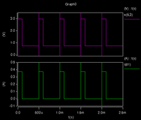 Current and voltage waveforms
Rfeedback = 2 Ohm -
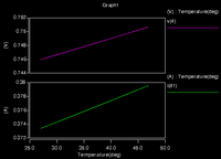 Effect of temperature sweep on current


Prototype Circuit
As a prototype for the final circuit, we designed the system on a breadboard. The circuits for each of the seven channels feeding the individual LEDs were small and compact. We modified the existing firmware to parametrize the number of output channels. Once the circuit was ready we connected it to the arduino and gave commmands to the Arduino through the USB port serial interface.

Intermediate Design
An intermediate version of the circuit was designed on a perforated circuit board using the 7 LED round-assembly configuration Luxeon LEDs. The purpose of this design was to run the system under actual operating conditions to verify that all the used circuit element ratings were appropriate for operation. Basically, check whether there were any faults like overheating in specific components.
The LED assembly was fastened with screws on to the flat round surface of the metallic heat sink, and separated by a thin layer of Heat Sink Paste. Wires were soldered onto the terminals of each LED. I color coded the wires as orange to represent positive and white to represent negative, for consistency. The perforated circuit board that I used had dimensions 7.5"x5.5" but this was larger than necessary. The heat sink average circular diameter was 2 5/16ths inch and so I used a hole saw of diameter 2 1/4ths inch to drill a hole in the middle of the circuit board to make the heat sink with the LED Assembly fit neatly through. I arranged and soldered all the circuit components in a circle around the central hole for compact connections to the LEDs.
All the individual circuit grounds were short-circuited and a common ground wire was exposed. Similarly all the positive terminals of the LEDs were short circuited and a common Vdd wire was exposed. The common ground and common Vdd were connected to a female Barrel connector terminal. The barrel connector was connected to the power supply using a standard power adapter. The Adapter specifications were Input: 100-240V 1A 50-60Hz, Output: 5V, 4A DC. The connector was a standard 2.5mm(ID)-5.5mm(OD) connector.
For each individual circuit the PWM signal input port was connected to a wire obtained from stripping an Ethernet Coaxial cable. The reason for this choice was because they could be easily wound together and made to emerge from the unit as a compact collection. The ends of the wires were soldered onto the pins of DIP male connectors so that they could just be slid into the Arduino connection sockets. To prevent the soldered wires from short-circuiting Heat Shrink was used to insulate exposed connections.
At this stage the Pins on the Arduino that were configured to provide the digital PWM output were (Digital) Pins 2,3,5,6,11,12,13.

PCB Layout
The application of the design is conducting visual experiments. Having the circuit configured to generate multiple different patterns on different LED collections in the backend enables a lot of flexibility in the front end optics. One of the ideas was to have 14 primary light channels and light output would be grouped as two separate groups to stimulate the center and the surround of the human visual system with flicker patterns.
To make the circuit as compact as possible and also get experience in laying out a Permanent Circuit Board in software. The software I used was ExpressSCH for making a schematic design and ExpressPCB for creating the PCB layout (that linked to the Schematic for verification purposes). Express PCB is a free software available for Microsoft Windows. This page ExpressPCB site has instructions for downloading and using the software. Other popular free Open Source software worth exploring are gEDA and Fritzing, links available here.
To calculate the acceptable PCB trace dimensions I used this website. ExpressPCB specified that according to their manufacturing process the traces usually come out as having a thickness of about 47 um. For the Ambient Temperature Parameter I used 27 degree C, with a tolerance of 15-20 degrees. The trace length I adjusted according to the layout dimensions. I made the PCB design with 2 Metal Layers single sided board design. The picture below shows the final layout.
The selection of Resistor Values were a combination of Simulation trials and back-of-the-envelope calculations. The value of maximum current flowing through an LED is 0.5A and with a 1.2 Ohm sense and feedback resistor the expected power is 0.3W. I chose a power value of 0.5W to have some headroom.
Arduino Pins to connect for PWM output: Digital pins 2,3,5,6,7,8,11,12,13,44,45,46
Initially I designed a PCB layout and it came back from the printers and some of the through holes were too small. Finally the important through hole/pad dimensions I used were: npn BJT
  Pad Size  = 0.056"
  Hole Size = 0.029" (+/- 0.004)
NMOS transistor
  Pad Size  = 0.075"
  Hole Size = 0.040" (+/- 0.004)
Multi pin Port(Inline Connector)
  Pad Size  = 0.075"
  Hole Size = 0.040" (+/- 0.004)
Barrel Connector Pads
  Pad Size  = 0.180"
  Hole Size = 0.125" (+/- 0.004)


Results
Circuit Measurements
We performed tests to measure and verify various aspects of our design. We wanted to verify that our circuit design did match the simulation, therefore part of the tests done were to verify the voltage and current. We also did tests to verify the stability of the output from the circuit over time. Finally we analyzed the spectral characteristics of the light emitted from the LEDs.
Circuit voltage and current measurements
We took voltage measurement across the LED and measured the current being drawn from our power supply, which in this case was the Arduino. The results showed that we had a 1.1V drop across the LED and that the total current being drawn from our power supply was approximately 90mA.
We also measured the voltage that was generated from a solar cell that was placed directly over one of the LED's. The voltage measure across the solar cell was 0.2V.
Note the PWM input from the Arduino was a square wave running at 2Khz and was modulated by a sinusoidal was that was at a 3Hz freq. See the following video to get a better idea of how the input wave looks like. [[1]].
Circuit temporal measurements
The LED Flicker device was left to run for 1 hour after the initial measurements were taken. We then remeasured the voltages and currents. The goal of this test was to verify the stability of the circuit.
After 1 hour the voltage drop across the LED was 1.1V and the maximum current drawn by the circuit was 90mA. The measured voltage across the solar cell was still 0.2V. This results did show that the circuit was stable after a 1 hour period.
LED Measurements
We obtained the LED spectral properties using a spectrophotometer. We got measurements for all the seven LED's that we were using. The graph below shows the spectral power distribution on the LED's. The second graph is the normalized version of the first graph. As you can see from the SPD curves the bandwidth of most of the LED's was narrow, apart from the white LED. Also the intesity of the blue and red LED seemed to be the greatest as shown by their SPD curves. We were expecteing to get high intensities and narrow bandwidths with the shorter wavelength LED's and lower intensities and wider bandwidths with the larger wavegth LED's. Our results did not show this and we attribute this mainly to the fact that we were not using the Luxeon 7 pack LED module that we had planned to use. This module has well matched LED's that will give SPD's that would be similar to what we expected. Also another fact is that our resistance values were not matched well with our LED's and this can be attributed to the fact that we did not have the right circuit models for the LED's to do a simulation and get the right resistance values.
- Spectral power distribution
-
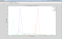 Spectral Power Distribution
 -
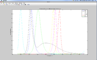 Normalized Spectral Power Distribution


The last set of spectral measurements we performed on the LED's was to capture the maximum intensity as we decreased the mean input voltage/power to the LED. We obtained a linear curve for all the LED's apart from one as shown in the curves below. We believe the curve that was not linear was as a result of that specific LED getting to it's saturation point before the peak power that was being provided.

System Optics (Future work)
The electronic circuitry design and assembly has been completed, however the design and integration of the optics of the system is still pending. This is an interesting challenge. The requirement is a system that is capable of transporting the light from the assembly to a remote location (this will likely be to an fMRI machine).
An idea is the use of a bundle of Optical fibers packed together and sheathed in a plastic tube coating. This would form a reliable and flexible transportation medium. A feature of this design is that bundles from the distinct 7 channel assemblies could be taken and combined in any pattern within the sheath for final delivery. A sample of something that might be possible to do is:

Conclusions
In conclusion, were able to succeed in achieving the goals we set. We build a 7 channel LED system that is portable, it was able to fit in a bread board. We verified the temporal stability of the system, a major requirement that the system had to meet We verified the spectral properties of the system. The result we got were not ideal but that could have changed had we used the Luxeon 7 channel LEDs. We also built some spice circuit models, which helped cut down the design time and will also be useful in the future should any modification need to be made.
The compact assembly of the intermediate design was successfully implemented and this is a working version of the design (without the transmission optics.). The design of a PCB layout of the entire circuit for 14 LEDs (driven by 12 independent programmable channels) has been completed and the current phase is that of the final circuit assembly and testing.
References
[Original Firmware(With 6 channel support)]
[Forked and updated firmware with 12 channel support]
Appendix I - Code and Data
Code
Spice code for simulated circuit: File:Circuit.sp.zip
Arduino code for driving LED circuit: File:LEDFlicker 12channel.zip
Prototype Data
Video of sinusoidal modulated PWM File:PWM modulated.zip
Video of test being run File:OneHourTest.zip
Appendix II - Work partition
Hardware assembly - Tirthankar Chatterjee
Schematic and PCB Layout Design - Tirthankar Chatterjee
Firmware edits - Isaac Chepkwony, Tirthankar Chatterjee
Help and advice from Robert Dougherty, Research Director Stanford Center for Neurobiological Imaging.