ChristineHitha
Introduction
Images captured under low-light conditions suffer from degradation, such as low visibility, low contrast, and high-level noise. Although they can be alleviated by professional devices and advanced photographic skills to a certain extent, the inherent cause of the noise is unavoidable and cannot be addressed at the hardware level. Without sufficient amount of light, the output of camera sensors is often buried in the intrinsic noise in the system. Longer exposure time can effectively increase the signal-to-noise ratio (SNR) and generate a noise-free image, however it breeds new problems such as motion blur. Thus, low-light image enhancement technique at the software level is highly desired in consumer photography. Moreover, such technique can also benefit many computer vision algorithms (object detection, tracking, etc.) since their performance highly relies on the visibility of the target scene.
This project attempts to understand the process of simulating low light condition images utilizing the open source Matlab tool ISETCAM created by Joyce Farrell and Brian Wandell [1]. The goal is to primarily learn and understand the ISETCAM pipeline in the context of low light imaging, observe the issues resulting from low scene luminance, and then to finally make changes to the ISP pipeline in the form of implementing various denoising algorithms in order to alleviate the issue.
Background
ISETCAM is split into four main modules: scene, optics, sensor, and processing.
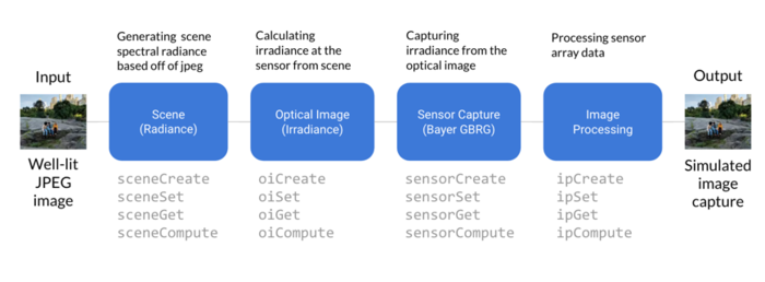
For each module, there are useful create, set, and get parameters as well as a display (window) function which allows the user to experiment with the simulation and then see the result. In addition, there are extra built-in functions which allow for even more customization. A good start would be in the script t_introduction2ISET.m found in /isetcam/tutorials/introduction. From there, we were able to build our own script to simulate the scene, optics, sensor, and processing pipeline.
From lecture, we learned the whole process of what will be simulated in ISETCAM. Some key concepts include radiance and irradiance which are critical to understanding the various ISETCAM modules and why they exist

To simulate the radiance portion of the lecture slide above, we utilize the scene module. Then, the irradiance is computed based off of radiance from the scene. The big difference between radiance and irradiance is that the first is talking about the source whereas the latter is talking about arrival. The sensor module then captures the computed irradiance into what a camera sensor would see or CFA. The one we used is the classic Bayer rgb array which requires demosaicking in the image processing module after. The shot noise presents itself in the sensor module and is relevant because noise becomes more apparent in low-light conditions since there are fewer photons hitting the sensor.
Another topic we covered in lecture was MSE as a metric for image quality (for example between an original and compressed copy). MSE is a popular way to compare two images, however does not relay accurate information of actual image structure comparison. The figure below is a good example of why MSE fails. Different kinds of error that introduce the same amount of error for MSE can have drastically different perceptual results. SSIM is much better because it measures similarity of a group of pixels based on luminance, contrast, and structure. In addition, the metric value that SSIM gives has an upper bound of 1 which makes it easy to evaluate a good SSIM measurement [2].

Methods and Results
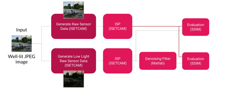
Our overall method pipeline is as follows. We take an image and use ISETCAM to capture an output image A based off of a scene generated from the original input image. Then we follow the same process again, but alter parameters to simulate low light conditions and acquire another output image B. We then apply denoising algorithms to the low-light image B and compare to image A using SSIM metric.
ISETCAM Simulation
In order to generate a low light image, we utilized ISETCAM which is an open source software simulator written in Matlab.
First, we generated a scene from a jpeg file and then adjusted the mean luminance of the scene in order to simulate low light conditions. From example, in the below image which originally had a mean luminance of 35.4 cd/m, we adjusted it to be less than a third of that to 10 cd/m.

   I = im2double(imread('img.jpg'));
   scene = sceneFromFile(I, 'rgb');
   scene = sceneAdjustLuminance(scene, 'mean', 10);

In the figure, the after illuminance energy has noticeably decreased by a magnitude of 10 due to the nature of the scene being low light. The effects of this will be seen during the sensor stage. There will be lower number of photons hitting the sensor which would yield a low light image as well as increase the shot noise of the captured image compared to a well lit scene. The problem with this noise will be seen and addressed later on.

Then, we had to use oiSet and oiGet routines to adjust the optical image parameters. Using diffraction limited optics, we were able to compute the optical image (irradiance) from the scene (radiance). Again, each module has display features so could easily see changes in each step.

The irradiance is then captured by a simulated sensor (NikonD100) which results in an array of output voltages. There are a lot of different sensor parameters as well as pixel structure properties. Here we just use the simple Bayer-gbrg sensor and set a few of its basic properties such as exposure. As you can see the captured irradiance in the second image is darker which is what we were aiming to do. Additionally, it is important to note that the sensor data looks green because in the Bayer pattern, green channels have double the sampling rate of red and blue channels. The final image will go through the ISET image processing pipeline and will undergo processing such as demosaicing and illuminant correction so that we can see the actual output image. Since this is a simulation, one could easily set a couple parameters such as auto exposure and noise flag to zero to get ideal output for a low light image that looks identical to the original jpeg image after processing.
   sensor = sensorSet(sensor,'auto exposure',true);
   sensor = sensorSet(sensor,'noise Flag', 0);
However, doing so doesn't tell us anything, so we opted to set our own exposure value and allowed shot noise in sensor capture.
   sensor = sensorSet(sensor,'exp time',0.030);
   sensor = sensorSet(sensor,'noise Flag', 1);

We used the following ISETCAM image processing method parameters: bilinear demosaicking, MCC Optimized conversion from sensor space to internal color space, Gray World illuminant correction, conversion from internal space to XYZ display primaries. As you can see, the result of the image after processing contains a heavy amount of shot noise which is where the denoising matlab algorithms come in.
Denoising after ISET ISP
Image denoising refers to the recovery of a digital image that has been impure by the noise. In case of image denoising methods, the characteristics of the degrading system and the noises are assumed to be known beforehand. With the creation of low-light images with ISETCam the image s(x,y) is blurred by a linear operation and noise n(x,y) is added to form the degraded image w(x,y). The main idea of this project is to have an added step to the ISET ISP to deal with the noise component at low light.

The idea is to convolve the image with the restoration procedure g(x,y) to produce the restored image z(x,y). The "Linear operation" shown in the figure is the addition or multiplication of the noise n(x,y) to the signal s(x,y).Once the corrupted image w(x,y) is obtained, it is subjected to the denoising technique to get the denoised image z(x,y).We shall compare and contrast a few denoising techniques after the discussing the characteristics of the kind of noise that corrupts the image.

While simulating the low light image the ISETCam is used to modelled the two major factors which affect the amount of noise in the image that is sensor temperature and light levels. When there is insufficient amount of light, the image majorly gets corrupted by what is called Shot noise. Photons (and photoelectrons) are quantum particles—this means that they can only come in whole numbers and the camera can never collect fractions of photons. Because of this and random statistical fluctuations, when collecting photons from an unvarying source over a set amount of time—say ten random 30 seconds intervals over the course of twenty minutes—it is highly unlikely that you will collect 20 photons every single time. Therefore this Shot noise is said to have a Poisson distribution. This noise has root mean square value proportional to square root intensity of the image. Different pixels are suffered by independent noise values. The photon noise and other sensor based noise corrupt the signal at different proportions.
Along with the Poisson noise there can be other additive noises that corrupt the signal. Denoising techniques have to be chosen depending on what kind of noise affects the image. In common there are a few types of image denoising : Spatial Domain, Frequency Domain and Wavelet Domain.A traditional way to remove noise from image data is to employ spatial filters. Spatial filters can be further classified into non-linear and linear filters. We tried our hands at deploying a few filters : Mean Filter, Median Filter, Weighted Median and NLM filters
Mean Filtering
It is one of the most simplest filter among the existing spatial filters. It uses a filter window which is usually square. The filter window replaces the center value in the window with the average mean of all the pixels values in the kernel or window.

As we can see that the Images have been blurred because of the filter and the edges are not reserved after the filtering. This is not the best we can get.
Median Filtering
It is also known as order statistics filter. It is most popular and commonly used non linear filter. It removes noise by smoothing the images. This filter also lowers the intensity variation between one and other pixels of an image. In this filter, the pixel value of image is replaced with the median value The median value is calculated by first arranging all the pixel values in ascending order and then replace the pixel being calcuated with the middle pixel value. If the neighbouring pixel of image which is to be consider, contains and even no of pixels, then it replaces the pixel with average of two middle pixel values. The median filter gives best result when the impulse noise percentage is less than 0.1. In our case as the noise levels were very high the Median filter also did not fare very well.
The mean filter can be represented by the following equation : 𝑓^(𝑥, 𝑦) = 𝑚𝑒𝑑𝑖𝑎𝑛{𝑔(𝑠, 𝑡)} 𝑤h𝑒𝑟𝑒 (𝑠, 𝑡) ∈ 𝑆𝑥𝑦 Here Sxy corresponds to the set of coordinates in a rectangular subimage window which has center at (x,y). The median filter calculates the median of the corrupted image g(x,y) under the area Sxy. Here f^(x,y) represents the restored image. For the RGB image, the channels are broken down to RGB and Median filtering is applied on each of the channels.
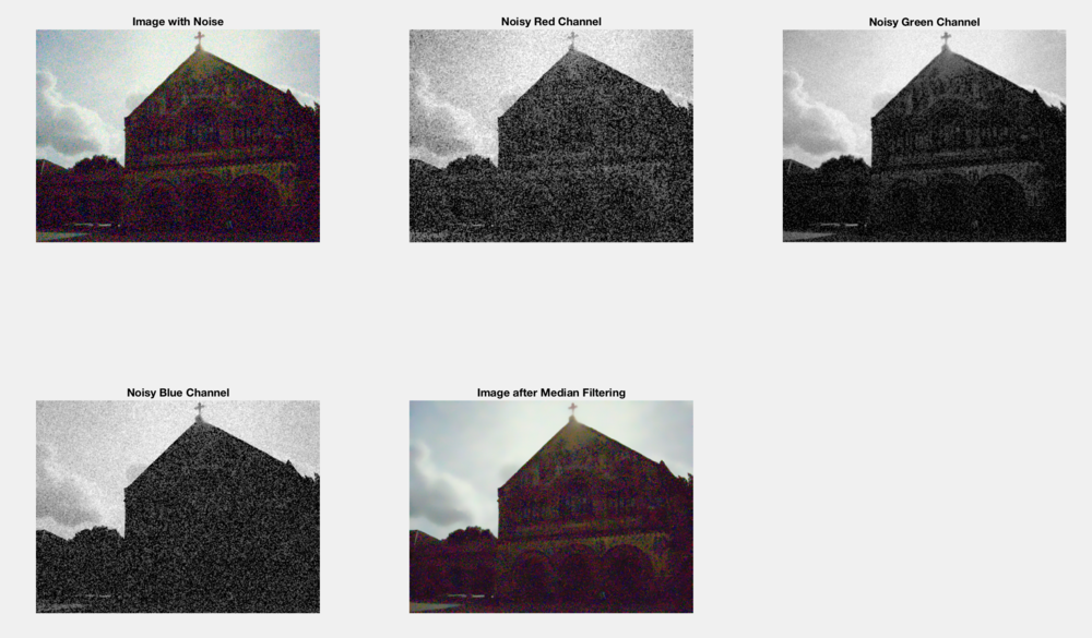
As we can see the images are not denoised to any great extent and this is basically to do with the kind of noise that we are dealing with.
NLM filtering
Image denoising is an inverse problem, and in general there is no solution. Nevertheless, there are many useful methods to deal with this problem, for example, the median filter, the Wiener filter, the bilateral filter, variational methods. The principle of the first denoising methods was quite simple: replacing the color of a pixel with an average of the colors of nearby pixels. The variance law in probability theory ensures that if nine pixels are averaged, the noise standard deviation of the average is divided by three. Thus, if we can find for each pixel nine other pixels in the image with the same color (up to the fluctuations due to noise) one can divide the noise by three (and by four with 16 similar pixels, and so on). This looks promising, but where can these similar pixels be found? The most similar pixels to a given pixel have no reason to be close at all. It is therefore licit to scan a vast portion of the image in search of all the pixels that really resemble the pixel one wants to denoise. Denoising is then done by computing the average color of these most resembling pixels. The resemblance is evaluated by comparing a whole window around each pixel, and not just the color. This new filter is called non-local means
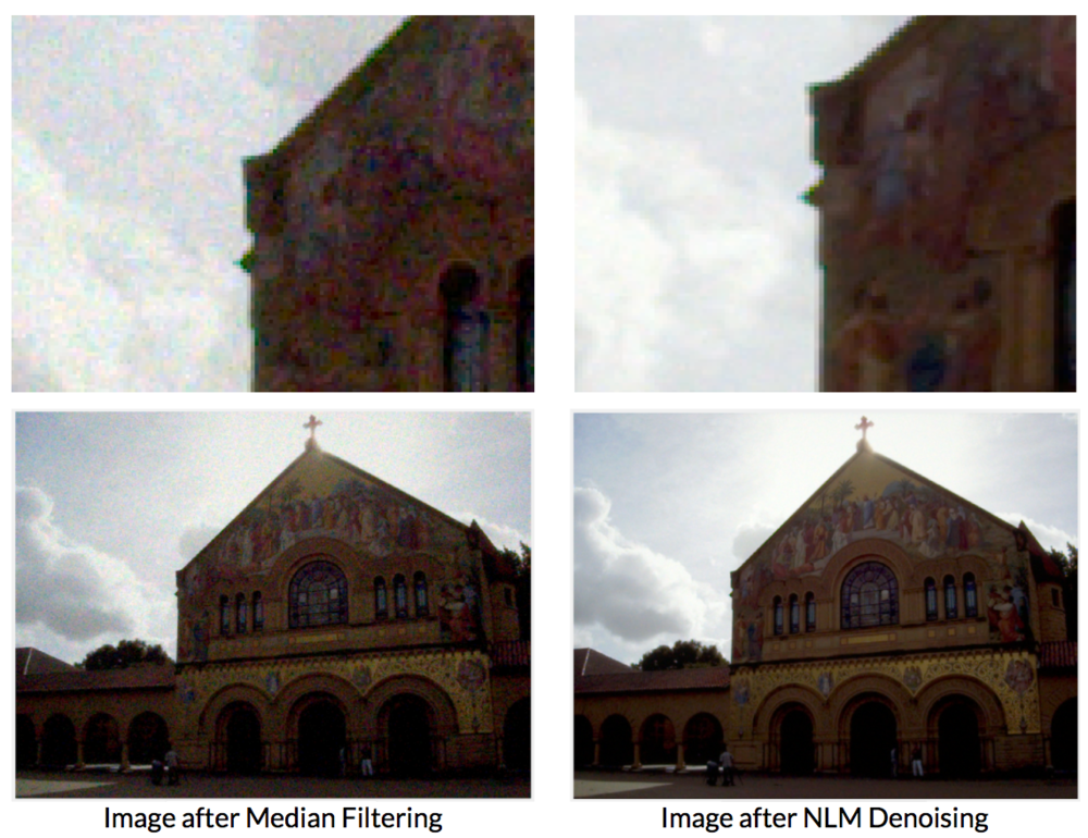
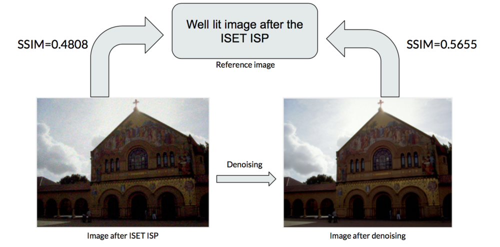
It is seen from the images that the NLM filter does a much better job than the linear Spatial filters like mean, median and weighted median filters. After we successfully added the denoising step on to the ISP pipeline, we also want to go ahead and test a very popular Image enhancement algorithm called the BIMEF. Our future work shall contain how we could probably use the ISETCam to make BIMEF an easier algorithm to deal with.
Conclusions
The idea of the project was to basically understand how the imaging of a low-light scene happens. We used the ISETCam software in order to step through each module and were able to understand what each step does to the image. We were successfully able to add a image denoising step to the end of the ISET ISP. With this the image is far less degraded from what it was before. We used the SSIM metric to understand the difference we were able to make to the pipeline.
BIMEF - An image enhancement algorithm
"Can we introduce this fusion mechanism of human visual system (HVS) to help build an accurate image enhancement algorithm? " This is the line in the paper that caught our eye. The BIMEF paper proposes a multi-exposure fusion frame- work inspired by the HVS. There are two stages in the framework: Eye Exposure Adjustment and Brain Exposure Fusion. The first stage simulates the human eye to adjust the exposure, generating an multi-exposure image set. The second stage simulates the human brain to fuse the generated images into the final enhanced result. The paper employs illumination estimation techniques to build the weight matrix for image fusion. Then they derive the our camera response model based on observation. The optimal exposure for our camera response models found and it is used to generate the synthetic image that is well-exposed in the regions where the original image is under-exposed. Finally, the enhanced results is obtained by fusing the input image with the synthetic image using the weight matrix.
We also were able to test the output of the ISP as an input to the BIMEF algorithm. The results look as follows:

References
[1] A simulation tool for evaluating digital camera image quality (2004). J. E. Farrell, F. Xiao, P. Catrysse, B. Wandell . Proc. SPIE vol. 5294, p. 124-131, Image Quality and System Performance, Miyake and Rasmussen (Eds). January 2004 Github Link
[2] Z. Wang, A. Bovik, H. Sheikh, E. Simoncelli, "Image Quality Assessment: From Error Visibility to Structural Similarity," IEEE Transactions on Image Processing, vol. 13, no. 4, April 2004.
[3] B.Thamotharan,‖ Survey On Image Processing In The Field Of De-Noising Techniques And Edge Detection Techniques On Radiographic Images ‖ Journal of Theoretical and Applied Information Technology 15 July 2012. Vol. 41 No.1
[4] A. A. Mahmoud, S. El Rabaie, T. E. Taha, O. Zahran, F. E. A. El-Samie and W. Al-Nauimy, "Comparative study between different denoising filters for speckle noise reduction in ultrasonic b-mode images," 2012 8th International Computer Engineering Conference (ICENCO), Cairo, 2012, pp. 30-36.
[5] M. Lang, H. Guo, J.E. Odegard, and C.S. Burrus,"Nonlinear processing of a shift invariant DWT for noise reduction," SPIE, Mathematical Imaging: Wavelet Applications for Dual Use, April 1995
[6] A Bio-Inspired Multi-Exposure Fusion Framework for Low-light Image Enhancement
[7] Chih-Yu Hsu‖ An Interactive Procedure to Preserve the Desired Edges during the Image Processing of Noise Reduction‖ Hindawi Publishing Corporation EURASIP Journal on Advances in Signal Processing Volume 2010, Article ID 923748, 13 pages doi:10.1155/2010/923748
[8] Ying, Zhenqiang & Li, Ge & Ren, Yurui & Wang, Ronggang & Wang, Wenmin. (2017). A New Low-Light Image Enhancement Algorithm using Camera Response Model. 10.1109/ICCVW.2017.356.
Appendix 1
Code link: File:Code RevChen.zip
Appendix 2
Christine was responsible for ISETCam low light image generation, Testing BIMEF and report writing Hitha was responsible for Denoising, Testing BIMEF and LECARM and report writing