Dual Fisheye Image Stitching Algorithm to 360 Degree Photos
Introduction
360-degree cameras provide utility by capturing all angles around the camera, or 360 degrees horizontally and 180 degrees vertically. This is different than the standard camera in your phone where the wide angle covers somewhere between 110 to 60 degrees, or a focal length of 10 to 25 mm [1]. There are many use cases to 360 degree cameras like virtual reality (VR) [2], generating digital twins for the purpose of cultural preservation [3], general photography, capturing events, and even virtual tours like Stanford’s [4]!
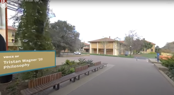
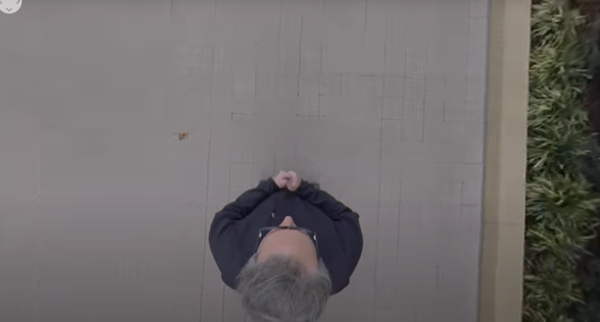
In Figure 1, you can see the Stanford virtual tour utilizing the 360 degree camera with the arrow symbol in the top left corner of the image. Additionally, they are utilizing editing features of the image to place notes to aid the tour. In Figure 2, you can confirm that the 360-degree video is indeed 360-degrees with the view of the man’s holding the camera’s head included in the tour.
There are two main types of 360-degree cameras: catadioptric and polydioptric [5]. Catadioptric cameras combine a lens (dioptric) and a mirror (catoptric) to take a 360-degree image. These types of cameras require calibration and are much larger as well as much more expensive than other types of 360-degree cameras. However, this type of camera geometry does not have as much camera parallax in the final image since there is not combining of multiple different images. Polydioptric systems involve stitching together images from multiple different wide-angle cameras. With these systems, the separate wide-angle, or fisheye lens, cameras have overlapping field-of-view’s so that the images are then able to be stitched together based on this overlap. The polydioptric systems are significantly more economical than the catadioptric systems, but do suffer from more camera parallax due to the required stitching in software.
The range of quality in different 360-degree cameras is large, as well as their cost. With the lower quality 360-degree cameras, more post-processing in software is required to avoid camera parallax. Something to note with the cheaper 360-degree cameras is due to their smaller contruction, there is significant vignetting across images. There, most likely, will be vignetting across most major 360-degree cameras before post-processing due to their wide aperture allowing light in at acute angles. However, this allows the technology to be more accessible to a larger audience. In this paper, the Samsung Gear-360 camera is used due to the widely available fisheye data online in addition to its lower cost.
Background
Since the Samsung Gear-360 is a polydioptric camera, software techniques for converting the fisheye lenses to one contiguous image will be discussed in this section. The specific camera in question has two fisheye lenses that are processed in software and joined to become one 360-by-180 degree image. Since each fisheye lens has a field-of-view of a little over 180 degrees, the two fisheye lenses will have some overlap that can be used to “stitch” the two images together.
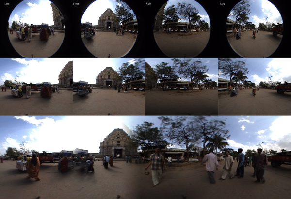
As seen in the top row of Figure 3, the image starts off being in a fisheye lense with some significant warping. Then, as seen in the middle row of Figure 3, each image is projected onto an equirectangular plane based on the assumption that the fisheye lenses keep the image in a spherical coordinate system. Lastly, the images are “stitched” together to generate one image.
As seen, the separate images in row 2 of Figure 3, have overlap across each one. This does introduce camera parallax as seen in row 3 of Figure 3. However, these overlapped features can be used to identify where stitching can occur. This can be done in a variety of ways including using machine learning technologies to complete feature matching across the different images, or the cross correlation to determine where the overlap occurs across individual images [5]. Another common way of determining the overlap is by using a homography matrix.
Lastly, there is a significant vignette on these images. To remove the vignette, post-processing in software can be used to remove the vignette including machine learning techniques and simple software techniques if the vignette model is known.
Methods
The fish-eyed lens stitching algorithm applied in this paper was implemented in Python. The algorithm can be described in the following key steps, which this paper will review in detail:
1. Parse out individual frames from a video including footage from the two fisheye lenses in the Samsung Gear-360. 2. Remove the vignette from the frame 3. Use geometric unwarping to map the pixels from each fish-eyed lens to an equirectangular projection 4. Remove the overlapping region between separate frames
Obtaining Individual Frames
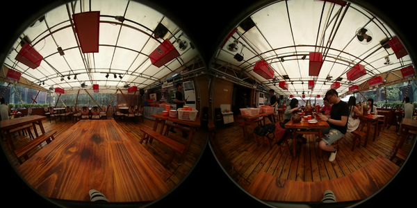
To test and validate the proposed stitching algorithm, a single frame of the video was necessary to work with. Each video’s frame includes two fish-eyed frames, laid horizontally. Each side of the frame has a little over 180 degree field of view and face opposite sides so that combined, they cover the full 360 degree view of the restaurant dining room; this can be visually confirmed by observing a small amount of horizontal overlap in the left and right edges of both frames in addition to some repeating features between the two images. Each half of the "two-frame" image is processed separately before combining again.
Removing Vignette
In order to estimate the vignette and model it, polynomial parameters estimated by Ho et al. were used [5]. These parameters were found by taking a fish eye photo using the Samsung Gear 360 camera of a white paper, normalizing the image by the white paper, and calculating the intensity rolloff towards the edges of the image. It was crucial that they normalized the image by its center because this makes sure that the difference in intensity due to lighting conditions or color of the paper isn’t impacting this model. The parameters were the following:
- p1 = 7.5625e-17
- p2 = 1.9589e-13
- p3 = 1.8547e-10
- p4 = 6.1997e-8
- p5 = 6.9432e-5
- p6 = 0.9976
The equation uses the format of the following equation where x is the distance from the white point, or the center of the image.
To generate a square image of the estimated vignette, the distance from the center of the image is used to then estimate the brightness using the above equation. With these calculated values, the final estimated vignette can be modelled.
In order to remove the vignette, the flat-field correction method can be applied [7]. This process follows the following equations where m is the mean of the vignette, F is the vignette image, D is a dark frame, and R is the image with the vignette that we are attempting to remove. Since we do not have a specific dark frame to compare against, and the model is relative to the center of the image itself, then it can be assumed that the dark frame is zero. C is the final image without the vignette.
Applying Equirectangular Projection
Fish-eyed lens images are circular in nature with the image occupying the center circle of a rectangular frame with a black void occupying the edges. To complete a fish-eyed image stitching, it is necessary to project each of these frames to fill the rectangular frame, two of which will then create a complete rectangular image when laid next to one another horizontally. A fish-eye image itself is a projection of the fish-eye lens, which has a latitude proportional to the radius from the center of the circle and an equal longitude.
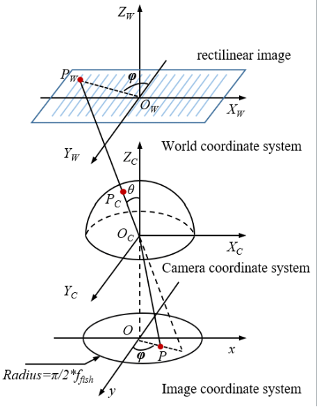
Each point in the image underwent this projection. An equirectangular projection first involves a transformation between the image coordinate system (P(x,y)) to a 3D camera coordinate system (P(Xc, Yc, Zc)). This 3D spherical coordinate system is a unit sphere, normalized to the radius of the image circle. To perform this step, three key image aspects should be known: lens field of view in degrees (f), image height (H), and image width (W).
A point’s spherical counterpart can be characterized using and , which can be thought of as the pitch and yaw of the spherical coordinate system, respectively. It is important that and be calculated in degrees for consistency. These are calculated with:
Each point’s new position value can then be found with:
Now, the points in the camera coordinate system are projected into the world coordinate system (P(Xw, Yw)), which represents the rectilinear coordinate system we would readily recognize as a standard image and which will serve as half of the final stitched image. represents the distance between the projected rectilinear center and the spherical point, or the length of Pw in figure [].
so that,
where
Now that each point has been projected to its rectilinear counterpart, the image will appear unwarped.
Removing Overlap
The number of frame columns required to remove the overlap was determined manually through an iterative process. With a significant amount of x- and y- misalignment as well as overlap, it is impossible to entirely align the image sides via removing frame columns alone.
Results
In Figure 5, the original, single frame taken from the video can be seen. The frame can be described as two circular images, laid horizontally and surrounded by black. A vignette around the radii of the circles can be seen, as well as overlapping objects on the far left and right edges of the circles to indicate a focal length slightly greater than 180 degrees. The following steps in the algorithm are applied to the left and right sides of the frame individually.
In Figures 6 and 7, the vignette model normalized to the white paper, as well as its inverse can be seen. It is the inverse vignette that will be applied to each image's half. The result of this can be seen in Figure 8.


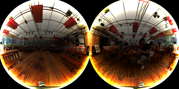
It is hypothesized that either the vignette parameters utilized are an overcompensation or the authors did not account for gamma correction. For clarity, the figures displaying results for equirectangular projection and overlap removal keep the vignette. Figure 9 displays the frame after the equirectangular projection is utilized. It can be seen that the circular images have been unwarped to encompass the entire rectangular frame.
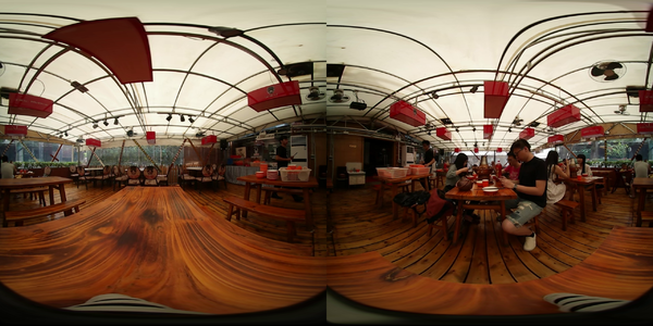
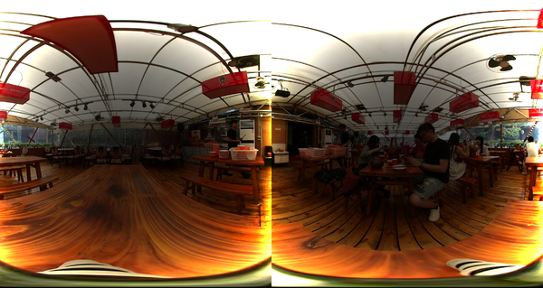
The aforementioned overlapping regions of the frame were removed by removing their associated columns, the result of which can be seen in Figure 10.
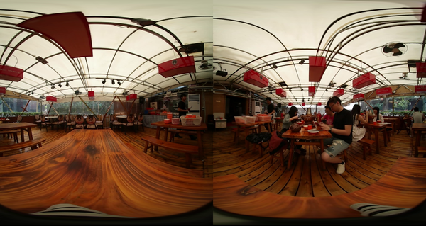
The final image with the vignette removed again can be seen in Figure 11.
Conclusions
Overall, we learned and validated a stitching algorithm for fish-eyed lens that includes removing vignetting, applying equirectangular projections, and overlap removal on a frame from a video.
Applying equirectangular projections was largely successful. Not noted in the papers we read on equirectangular projection from the spherical fisheye lens, requires some form of interpolation to “fill in the blanks”. The geometry transformations between the initial 2D image’s frame to the camera lens’ spherical frame, to the final image’s projected 3D frame were largely intuitive and logical, and we were able to turn the two side-by-side circular images into a single rectangular frame. The pitch and yaw calculations done in Ho et al. included a 0.5 degree offset, which we did not see duplicated in other studies. However, we saw that the equirectangular frame projection included some of the surrounding black circles without this offset [5] [8]. It is hypothesized that this offset accounts for any tilt of the camera lens itself when documenting the images, but future work could study under which scenarios these offsets should be applied.
Next year, it would be worth investigating automating as many aspects of our algorithm as possible, including removing overlap (which was completed by eye here). This algorithm should be applied to more frames from different camera lens to further validate its feasibility.
The vignette removal using the flat-field correction did not work, evidently, and seemed to overcorrect for the vignette. This could be due to multiple different reasons, as Ho et al. did not specify whether the color space of the image was linear or gamma corrected, or if the vignette model they estimated applied to the fisheye shaped lens or the rectangular projection [5]. We can assume, however, that due to the positioning of the section discussing the vignette model, that the vignette correction was, in fact, applied to the fisheye lens before it was projected onto an equirectangular plane. They also did not discuss with the correction of the vignette whether that be done using the flat-field correction method or not, so this was another assumption we made.
OpenCV’s VideoCapture class does not apply gamma correction when importing frames which means that when correcting the vignette we assumed that the frames have a linear color space, or sRGB. In the future, it would be worth trying different gamma values when gamma correcting the frames before applying the vignette removal. In addition, it could be useful trying different vignette removal algorithms like using Gaussian filters, or deep learning based methods. There are also methods of removing the vignette that involve simply looking at the intensities across the image you are trying to remove the vignette by stabilizing these intensities. Usually, there are no images where the intensities predictably roll-off towards the edge of the image, so this method works with the vast majority of images.
References
[1] Different Viewing Angles For Your Camera&text=Wide Angle%3A Lenses covering a,length of 25mm to 65mm(https://www.brickhousesecurity.com/hidden-cameras/field-of-view-explained/#:~:text=The%20Different%20Viewing%20Angles%20For%20Your%20Camera&text=Wide%20Angle%3A%20Lenses%20covering%20a,length%20of%2025mm%20to%2065mm).
This article covers the different viewing angles for different types of cameras.
This article introduces the Facebook surround 360 VR system.
[3] https://weiss-ag.com/culturalheritage/
This article talks about how 360-degree cameras can be used to help preserve cultural heritage.
[4] https://visit.stanford.edu/tours/virtual/
This is the Stanford Virtual Tour.
[5] T. Ho and M. Budagavi, “Dual-fisheye lens stitching for 360-degree imaging,” 2017.
This is a paper that introduces a novel stitching method for 360 degree cameras using the Samsung Gear 360.
[6] https://www.kscottz.com/fish-eye-lens-dewarping-and-panorama-stiching/
This article covers the fish eye lens dewarping as done by someone else.
[7] https://en.wikipedia.org/wiki/Flat-field_correction
This wikipedia page covers the flat field correction method to remove vignettes.
[8] ye, Yaozu & Yang, Kailun & Xiang, Kaite & Wang, Juan & Wang, Kaiwei. (2020). Universal Semantic Segmentation for Fisheye Urban Driving Images.
This paper provides an explanation of fish-eyed lens equirectangular projections.
Appendix
Appendix 1
Here is a link to the code: https://github.com/naviatolin/image_reconstruction_360/tree/main
This repository contains the code which can turn two Samsung Gear 360 fish eye lenses into one singular image. The data we used along with the result frames are all included in the 'test_frames/' folder. In order to run this code, please use the 'main.py' file.
Appendix 2
The code was written in a pair programming way with one of us driving and the other trying to direct/conduct research on the other persons laptop. The programming was done in an iterative and multi-session manner. The presentation was made and practiced in a similar way. The paper was worked on synchronously together as well and split evenly.


