JShakyaPsych2012Project
Back to Psych221-Projects-2012
1.Introduction
Hyperspectral images contain spectral response from each pixel in the scene and hence contain more information than standard RGB image. Based on exact shape of the spectrum of each pixel, it is possible to identify the material composition and distribution in the reflecting surface. If it is a painted surface, it is possible to identify the exact color with same spectral response. In recent years, there has been many advancement in fluroscent microscopy, which uses light spectrum to identify molecules in biological samples. Using hyperspectral camera, we can identify fluorophores and hence spatial distribution of certain molecules. Different illuminants used in cameras have different spectrum and hence using hyperspectral camera, we can identify the illuminant and correct for proper illumination.
The RBG image captured by digital cameras contain 3 colors per pixel. However each pixel in fact has its own charateristic spectrum based on reflectance of that pixel. In RGB cameras, the spectrum is reduced into 3 values (R,G and B) by placing 3 RGB filter in front of 3 CMOS sensors. These filters have their own transmission spectrum so that each filter passes only a limited band of spectrum through it. The 3 number for R,G and B are obtained by multiplying the image spectrum by the corresponding filters. In contrast to RGB camera, a hyperspectral camera, in fact captures the entire spectrum. For doing that the hyperspectral camera receives a line image, passes through a prism which decomposes spectral composition and then various CMOS sensors are different wavelengths capture intensity at each wavelength. In such hyperspectral camera the full 2D view is captured by rotating the camera to acquire successive line images. However this takes time and also requires physical motion in the camera. Often due to scanning nature, it requires scene to be rather static so that it doesn't change while it is scanning. In this project we are proposing a Camera System which can capture hyperspectral images the same way as digital camera in a single shot.
2.Methods
Interferometric Color Filter

Human visual system can only detect intensity and frequency (hence wavelength). However light has various other properties such as polarization, phase etc which our eyes cannot see. However through interference phenomenon we can convert phase difference of two light sources into intensity which we can see. <br\> There has been many recent usage of interference techniques in imaging systems. One of such application is use of interference to create mirrors that selectively reflect a particular wavelength. Such mirrors can be used in designing MEMS based displays. One of such interferometric display technlogies is Mirasol. On other hand the same interference phenomenon can be used to create color filters. When light get transmitted through each partially reflective surfaces (mirrors) seperated by some distances, based on the seperation distance (L) and wavelength of light it is possible to have either constructive or distructive interference. Such a device is called Fabrey-Perot Interferometer. It consists of two semi-transparent mirrors seperated by transparent medium. When light enters the first mirror, part of it is reflected and part of it is transmitted. A portion of transmitted light gets reflected by second mirror, a portion of which gets transmitted back out of first mirror and rest gets re-transmitted in the direction of original incident light. For a particular wavelength and choice of L, if the phase difference between light reflected from first mirror and second mirror is 2*n*pi, they distructively interference hence there is full transmission. The roll-off and width of passband depends on Reflectance of each mirror. The Transmission as function of wavelength and seperation is given by:

<br\>
<br\> Where R1,R2,T1 and T2 are reflectances and tranmittances of Mirror 1 and Mirror 2 respectively. L is the seperation between mirrors and is incident angle. <br\> If we only consider normal incident, and , we get,<br\> <br\> which is simply, <br\>

<br\>
Let be the total range of wavelength of interest. Note that for single peak filter this ranges is . If the bandwidth of a passband is known we can calculate the reflectance required of each mirror by solving following equation.<br\> <br\> Where is the bandwidth of filter at transmission peak corresponding to L. Since the bandwidth is a function of R, it needs to be decided during fabrication and is not chageable during operation. <br\> <br\> <br\> <br\> <br\> <br\> <br\> <br\> <br\> <br\> <br\>
MEMS Tunable Interferometric Filters
-
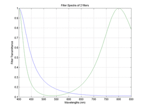 Figure 4: Filter Transmission for 2 to 16 Filters

The interferometric filter described above can be built as a MEMS device, where two semi-reflective layers on glass substrate are seperated by air. By using electrostatic drive, it is then possible to change the seperation between two mirrors by applying certain voltage. <br\>

<br\><br\><br\><br\><br\><br\><br\><br\><br\> The seperation is a direct function of applied DC voltage, when other factors such as restoring spring force is constant. The voltage required for a particular seperation can be calculated by solving force equilibrium equation. There are mainly two forces acting on the movable mirror, viz the restoring force from the mouting and the electrostatic force. The voltage required to get certain seperation is given by: <br\> It should be noted that the mirrors can only have travel before electrostatic force overcomes the restoring force and the mirros collapse to each other. There are various technique applied in actual device which allows extending the travel range, such as after some travel, the spring become more stiffer, the optical path between mirrors can be made different from physical path using high refractive transparent coating on each mirror.
Interferometric Hyperspectral Image Sensor
Using above described Tunable color filters, it is possible to take multiple images of a scene applying different filter each time. If the filters' spectral resolution is higher than highest frequency content (in wavelength space) in the scene spectrum, it is possible to represent the scene using images captured with different filters. The number of filters required and their sharpness will depend on nature of the scene. Since most of the natural scene don't have rapid variations in spectrum, it is possible to capture natural hyperspectral scenes using less number of filters than that will be required for spectrum with sharp rapid variations. For example capturing absorption or emission spectra of a many species of molecule will require large number of filters to preserve the shape of the spectrum. In such cases, higher order and hence sharper Interferometric Filters can be used to capture spectral information around sharp peaks and wider filters elsewhere.
In the perceived Hyperspectral Sensor Array, the Interferometric Filter will be fabricated on top of CMOS Sensor Array and each filter will be routed to X and Y electrodes for XY addressability with CMOS pass transistors to select or deselect each filter. Each filter pixel, since is a two layer conductive material, once voltage is applied, the Voltage is retained in the inherent capacitance of the device. Since each filter is independently addressable, it is also to implement dynamic algorithms in the Camera such that filter pixels at some portion of the sensor array can be fine sampling at different wavelength than that at other part of the sensor array. Although it looks simple, there are many practical issues we might run into during actual implementation.
Practical Limitations
There are various sources of non-ideality in practice which needs more thorough analysis. Following are some of the issues that might become evident during actual implementation:
- The mirrors can have some absorption.
- The mirrors have some tilt and hence transmission spectra is no uniform.
- The mirrors can also have curvature due to mouting on the sides, which further diffuses the passband.
- The mirrors can have process and fabrication variations which will change the amount of voltage that needs to be applied to get certain seperation different for different pixels.
- The mirrors can exhibit stiction issues.
For this project we are limiting the analysis to the theoretical feasibility and analysis of number of filters required for various types of scenes.
3.Results
There are two various ways we can use the Color Filters by using different algorithms. Since each filter pixel is independently addressable, we can be focusing on different parts of the spectrum in different pixels. By using dynamic algorithm, it is possible to limit using only the number of filter required to represent a particular scene. Following were two algorithms suggested during this project.<br\> <br\> 1.Using Predetermined Number of Filters: By using hyperspectral data captured using other techniques, we can find the number of filters needed for a particular type of scene. In this project we found that for natural scenes, we need around 7-8 filters to correctly represent the spectrum at each pixel. It was noted that dE across all pixels is less than 1, if we use 8 filters. Following animations show how the error changes as we increase the number of filters. In this scheme, the total range of wavelength (400nm - 800nm) is progressively divided up to 16 parts (17 filters).
- Figure 6: Bosch Image Progressive Spectral Estimation
-
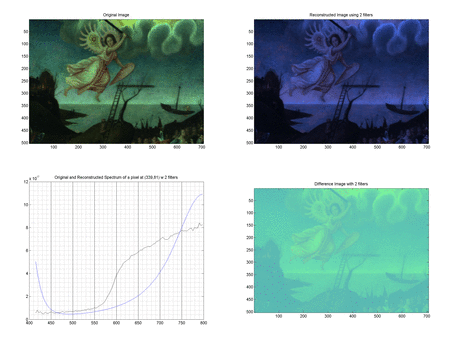 Figure 6 - Bosch Image with filter = 2 - 17

- Figure 7: Sellaio Image Progressive Spectral Estimation
-
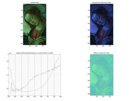 Figure 7 - Sellaio Image with filter = 2 - 17

<br\><br\><br\><br\><br\><br\><br\><br\><br\><br\><br\><br\><br\><br\><br\><br\><br\><br\><br\><br\><br\><br\><br\><br\><br\><br\> Since the natural scenes have spectrum from various sources diffused across space, there isn't much high frequency component in the spectrum. To further illustrate the we can use such as camera to represent spectrum with higher frequency content, we used spectrum of cy3 fluorophore to generate a flat image and it was simulated using the same algorithm. Figure 8 shows the spectrum of cy3 and shows how estimation converges to the actual spectra, when we reach about 16 filters.
- Figure 8: Convergence of estimation of Cy3 spectrum
-
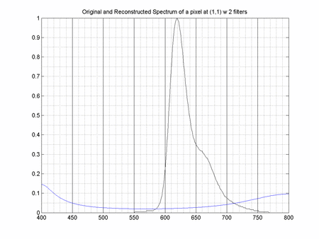 Figure 8 - Cy3 Spectrum with N = 2 - 17

<br\>
2.Progressive Dividing Algorithm: By using the difference between data captured in presvious set of filters and new set of filters, we can find which portion of the spectrum still contains more information. Hence we can progressively divide the spectrum into smaller sections until there is no more information. Since each filter is independently addressable, it is possible to peform this operation on each pixel without dependence on other pixels. Hence the camera can be sectioning one part of the spectrum in one part of the scene and sectioning different part of the spectrum in different part of the scene. This algorithm leads to less number of required filters as compared to previous algorithm. However it requires setting reflectance of the mirror and hence bandwidth of the passband somewhat arbitrarily narrow knowing that we are going to be dividing the spectrum on need basis.
<br\><br\><br\><br\><br\><br\><br\><br\><br\><br\><br\><br\><br\><br\><br\><br\>
4.Conclusions
This project described a concept Hyperspectral Camera using Interferomteric Color Filters. Although there has been many application of Interferometric Techniques, concept of designing Color Filter using interference hasn't yet been reduced to practice. The project was motivated by the fact that capturing Hyperspetral Images using horizontal scanning has some limitations as point out earlier. Through simulation of existing data, it was shown that it is possible to represent the hyperspectral images using lower dimension and it can further be optimized by dynamic algorithms which allows finer spectral resolution at points in spectrum having more information. During the project various algorithms were tried out including principal component analysis (PCA), however since we didn't have choice of designing filters with any shape, and shape of filters are already governed by interference equations, we had to abandone that approach. The best two schemes were presented in this paper and further exploration of this ided could lead to better way to do spectral sectioning. Finally through simulation the concept including the algorithms were demonstrated. Although it was conceptually validated, there are many practical limitations in designing such filters and hence future work should focus on analyzing and solving some of those practical challenges.
5.References
- US Patent US6400738, “Tunable Fabry-Perot Filters and Laser”
- Fluorophore Spectra, “http://www.invitrogen.com/site/us/en/home/support/Research-Tools/Fluorescence-SpectraViewer.html”
- Wikipedia, "http://en.wikipedia.org/wiki/Fabry%E2%80%93P%C3%A9rot_interferometer"
- Brian A. Wandell, “Foundations of Vision”
- Ralf Menzel, “Photonics: Linear and Nonlinear Interactions of Laser Light and Matter”
- Chang Liu, “Foundations of MEMS”
- B.E.A. Saleh, M.C. Teich, “Fundamentals of Photonics”