LeeKosarajuSankaranarayanan
Introduction
The human visual system responds to only wavelengths of light in the range 400-700nm. Although not perceived by the human eye, light in the wavelengths from about 800-2500nm, which represents the near-infrared (NIR) region of the electromagnetic spectrum, is rich in information about the scene that can be utilized for a variety of applications. Remote sensing community has a long history of making inferences from NIR data. Since silicon is sensitive to these wavelengths, near-infrared capture could be enabled in digital cameras and the information could be used to enhance photographic images. A number of such applications have been proposed by researchers [1,2,3,6,8,9]. In our work, we are concerned with evaluating some of these algorithms used for contrast enhancement, haze removal and skin smoothing.
As these applications work independent of each other, methods and results are discussed separately for each of these.
Contrast Enhancement
Motivation

Source: [7]
Images taken under normal exposures suffer from lack of contrast under low light conditions. Long exposure shots are not suitable to fix the problem if there are moving objects in the scene. On the other hand, NIR images tend to have a better contrast than the visible images. The reason we think NIR images have better contrast is because silicon has a better quantum efficiency in the near-infrared than in the visible regions. From Figure 1, we can see that the quantum efficiency in the NIR bands is 50-60% greater than that in the visible portions.
Zhang et al suggest using near-infrared images to enhance the contrast by a suitable transfer to the visible image [8]. A slightly different way to use NIR for contrast enhancement would be to use an NIR flash instead of a visible flash as proposed by Zhang et al [9]. The advantage of using such a method is that one no longer has to deal with the artifacts caused by a visible flash.

The goal of this section is to understand the algorithmic and implementation details of the technique proposed in [8].
Methods
Basic Algorithm
Algorithms to transfer contrast from NIR to visible tend to follow a common template. The main components of the template are
- Filter the intensity images (visible and NIR) using an edge-preserving filter (Bilateral filter, Weighted Least Squares filter, etc.). The reason for filtering is that a direct contrast transfer on unfiltered images can destroy some of the detail in them. The filter outputs are called base images
- Perform a histogram transfer so that the distribution of intensities in the visible base image looks like the intensity distribution in NIR base image.
- The details(or high frequency content) in the visible image can also be enhanced using the details in the NIR image using some kind of weighted mean. There are two different ways of defining the detail image
- Detail Image = Original Image - Base Image
- Detail Image = Original Image / Base Image
where -,/ denote pixel-wise subtraction and division respectively.
- Combine the modified base layer and enhanced detail layer to get the enhanced image.
- Enhanced Image = Contrast Enhanced Base Image + Enhanced Detail Image
- Enhanced Image = Contrast Enhanced Base Image * Enhanced Detail Image
depending on how the detail layer was defined.
Particular Implementation
Our work follows the algorithm described in [8]. The workflow is shown in Figure 3.


The major steps in the algorithm are as follows:
- Obtain a HSV image from the RGB values. 'Value' dimension of the HSV image gives the brightness distribution in the image.
- Apply a Haar transform on the visible image brightness and the NIR image. The Haar tranform gives 4 images for every input image, each 1/4 the size of the original image. They represent a blurred version of the original image, horizontal, vertical and diagonal differences of the pixels in the original image. Let V,VH,VV and VD denote the blurred, horizontal, vertical and diagonal difference images respectively. N,NH,NV and ND are their counterparts in NIR. An example of Haar tranform output can be seen in Figure 4.
The reason for transforming the image using Haar wavelets is that the difference images contain rich textural information which can be destroyed by large-scale contrast transfer. - Compute Weighted region mask :
All regions of the image do not typically suffer from poor contrast. This algorithm uses an adaptive mask to indicate the amount of contrast enhancement needed, for each pixel. Let and denote the value and saturation at a given pixel . We calculate two weights and based on the following heuristic:- Pixels with very low or very high value and very low saturation suffer from poor contrast.
We can translate this heuristic into a formula as shown below
where are the probabilities that a pixel in the image will have a saturation = and value= respectively. - The reason for including probabilities is so that enhancement is performed only if large chunks of the picture suffer from poor contrast, which according to [8] gives better perceptual results.
- Now the weighted region mask is given by
Higher values for a pixel in W indicates increased need for contrast enhancement. This can be seen in Figure 5 where regions corresponding to trees have a poor contrast and hence have a higher value in W compared to the sky or the grass. - Note: The reference paper does not use and this restricts the maximum value for any pixel in to be 0.2 which we found to be very low for the images we used. Hence was set to a value between 2 and 3 to increase the range of values in
- Pixels with very low or very high value and very low saturation suffer from poor contrast.
- Transfer Contrast:
For reasons mentioned previously, a bilateral filter is applied on both V and N. Let Vb and Nb represent the output of the bilateral filter. The detail images Vd and Nd are calculated as follows
A histogram transfer is used to modify Vb based on the histogram of Nb. The values of pixels in Vb are adjusted until the probability distribution function looks like that of the pixels in Nb. Let Vb' be the output of the histogram transfer. A contrast transferred image V' is obtained from the new base layer Vb' using
where . is pixel-wise multiplication - Transfer Texture:
Texture is enhanced from the information in NIR using the following method
VV' and VD' are obtained similarly - An inverse Haar transform is applied on V',VH', VV' and VD' to get the enhanced Value image(of HSV). By using the original H and S values we can get an enhanced visual image.
NIR Band Selection
Since we had access to multiple different NIR bands from a hyperspectral image capture, we could use any of those to perform contrast enhancement. In order to automate this process, one needs metrics that indicate the amount of contrast in each band to reason about their choice. We use the following two metrics to guide the process of band selection
- Mean luminance in the image
- We would like the mean luminance(normalized) to be as close to 0.5 as possible, so that the image is neither too dark nor too bright.
- Variance of luminance across all pixels
- We would like the pixels to have a large variance about the mean for better contrast.
By plotting the mean and variance of luminance of the image for different NIR bands, one could choose the band they would like to use for contrast enhancement.
Example 1
From the mean and variance plots shown below, it can be seen that any choice of between 800nm and 900nm will be effective because in these bands the mean luminance is highest (~0.4) and variance is greatest.
- Contrast Enhancement, Outdoor Image
-
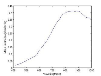 Figure 6:Mean Luminance
 -
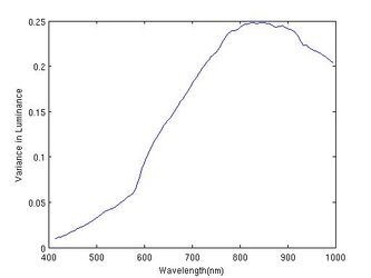 Figure 7: Variance in Luminance


Example 2
Here is a more tricky example, where the NIR bands are slightly brighter than the visual bands (greater mean luminance) but the variance is seen to be better in the visual bands. While it may seem that transferring variance information from a visual band, say to the NIR band could produce better results, such transfers are noisy and we found it to affect the final contrast enhanced image. So we decided to just use as is.
- Contrast Enhancement, Outdoor Image
-
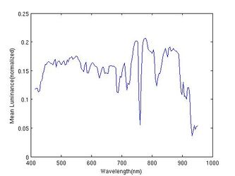 Figure 8:Mean Luminance
 -
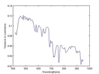 Figure 9: Variance in Luminance


Results
Shown below are results we obtained using the algorithm discussed above.
- Contrast Enhancement, Indoor Image
-
 Figure 10: Original Image
 -
 Figure 11: NIR band
 -
 Figure 12: Contrast Enhanced Image


- Contrast Enhancement, Outdoor Image
-
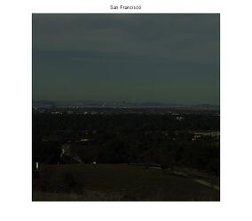 Figure 13: Original Image
 -
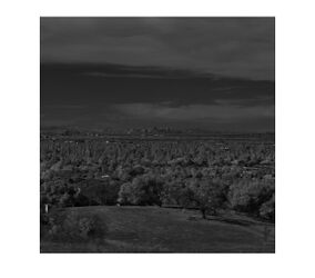 Figure 14: NIR band
 -
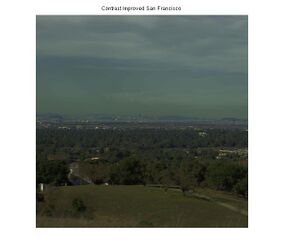 Figure 15: Contrast Enhanced Image


We can clearly see from the results that there is good contrast enhancement in the final images. This method also requires very few tweaks, the only parameters required to be set are
- Choice of NIR band with best contrast
- Window size and for the Bilateral filter.
- for weighted region mask
Our observation was that these parameters exhibit consistent behavior across different images i.e. their value only needs to be changed in a narrow range to get optimal results.
Bilateral Filter parameters
Since most of the detail is already captured in the Haar difference images, the algorithm produces very similar outputs for a wide range of values for the Bilateral filter parameters.
Run time
The algorithm was found to be very fast and took less than 2 minutes on a machine with Dual-Core AMD Opteron(TM) 2220 processor.
To summarize this section, we have validated claims that there is better contrast in certain NIR bands than in the visual bands, analyzed an algorithm that exploits this property to enhance photographs using NIR information, presented a way to choose which NIR band to use in case of hyperspectral capture and looked at the performance of the algorithm across different values for the parameters.
Haze Removal
Motivation
Landscape images are often degraded by an atmospheric phenomenon called haze which results due to the scattering of incident photons by the aerosol particles suspended in air whose size is lesser than where is the wavelength of the incident photons. This scattering of light is due to a phenomenon called Rayleigh's scattering which is given by where is the intensity of the scattered light, is the intensity of the incident light. Sky appears blue as blue wavelength being the shortest in the visible range is the most scattered. Hence atmospheric haze also appears blue. Haze causes a loss of detail and contrast as the scattering has an attenuation and smoothing effect. It is particularly significant in landscape images as the distance of the object from the observer is more and the background such as mountains and clouds appear very hazy. From Rayleigh's scattering, it is evident that there is much less scattering of light in longer wavelengths like the Near Infrared compared to the visible. Hence, an efficient way to eliminate haze without the use of a separate scattering model would be to use multiresolution decompositions on both visible and NIR images. We propose to do this using Weighted Least squares filters as they are fast and avoid halo artifacts and then synthesize dehazed images on a pixel by pixel basis using a criterion that maximizes contrast.
Applications
There are other interesting applications to haze removal as well. The fact that all colours have an identical near-infrared response, but black stays black due to the different pigment could be used to detect the composition of dyes in clothing thus predicting whether it would be warmer or cooler clothing based on black detection.It could also be used for Forgery prevention – real black ink could be distinguished from black obtained by combination of different colors.

Methods
Hyperspectral data which has spectral bands spanning the entire range of visible and NIR regions from 400nm to 1000nm where the visible range between 400 to 700 nm and the NIR range between 700nm to 1000nm was used to extract the respective spectral images of visible and NIR required to implement Schaul's dehazing algorithm. Though general contrast enhancement techniques could be used for haze removal, these do not apply specifically to the local regions of the haze and degrade even the haze free regions due to the global nature of contrast enhancement techniques such as histogram equalization/matching. Few physics based techniques for automatic haze removal have been proposed which used haze imaging equations which were the sum of two terms namely direct attenuation and airlight. But these techniques are complex as opposed to the algorithm proposed by Schaul et alwhich is fast and does not need heuristics for airlight and haze detection.
The algorithm proposed by Schaul et al [6] uses Weighted Least Square(WLS) [10] filters as opposed to Bilateral filters as the latter, though it acts as an edge preserving filter , performing well to decompose an image into a base layer and a single detail layer, is not well suited for progressive coarsening of images whereas the WLS filters enable decomposition into a base and detail layers of different scales.
Schaul et al's Algorithm [6]
-
 Original Input

- Analysis Obtain the 7 approximation layers for the input image in both the visible and NIR spectral bands
-
 NIR Approx layer
 -
 Visible Approx layer


Obtain the 6 detail layers for the input image which are the differences between k-1th and kth approximation layers
normalized by dividing by the kth approximation layer.
-
 NIR Detail layer
 -
 Visible Detail layer


- Criterion Maximize the contrast by extract the maximum of the detail values of visible and NIR spectral bands on a pixel by pixel basis
- Synthesis Synthesize the new dehazed image using the criterion above for the detail component which is fused with the 7th level approximation layer.
-
 Dehazed Output Image after fusion

Results
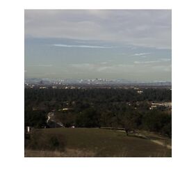
In order to evaluate the performance of the algorithm, a sample test set of landscape images was used and a quantitative metric based on mean square error of the normalized output image using the corresponding normalized polarized image as the base for comparison was developed. It was found that the mean square error when NIR image at wavelength 903 nm was used was much lower than that when the corresponding NIR image at a shorter wavelength of 757 nm was used thus validating the rationale behind Rayleigh's scattering effect which states that longer wavelengths have much less scattering due to which we chose longer wavelength NIR spectral bands to fuse with the visible spectral bands so as to synthesize a dehazed image. It is difficult to arrive at the exact NIR wavelength to be used for the application of dehazing the images as it is difficult to quantify haze. A brute force approach would be trial and error in the longer wavelength regions of NIR to arrive at the right wavelength. One possible approach to zero in on the right wavelength would be to calculate the sum of the gradients of the hazed and dehazed images and extract the wavelengths of the corresponding NIR image that would give the highest difference in the sum of gradients of dehazed and hazed images as the dehazed images would have a higher gradient sum due to edge sharpening effect as opposed to the scattered hazy images. Also better dehazing performance with NIR in the 900 nm range can be attributed to the peak in the silicon responsivity curve which is around the same range due to which a more detailed image is captured in the NIR region of that particular range.
- SanFrancisco when NIR at 757nm
-
 Hazy image
 -
 NIR image at 757nm
 -
 Dehazed image


- SanFrancisco when NIR at 903nm
-
 Hazy image
 -
NIR image at 903nm
-
 Dehazed image


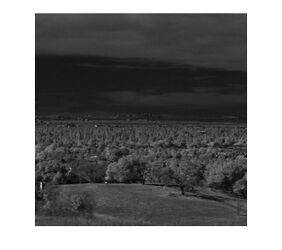
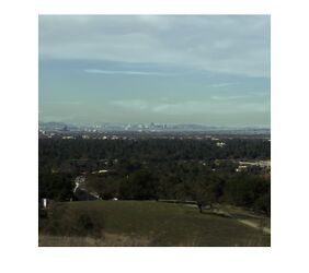
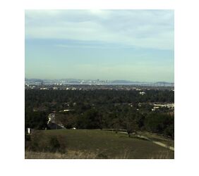
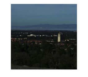
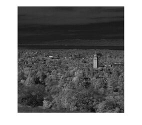
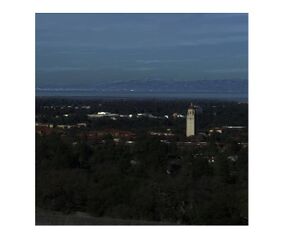
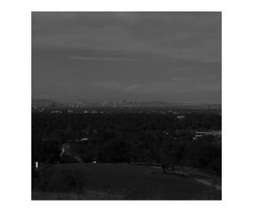
- Stanford Dish when NIR at 903nm
-
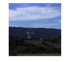 Hazy image
 -
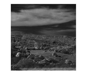 NIR image at 903nm
 -
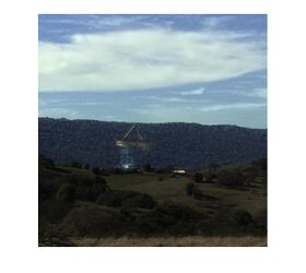 Dehazed image


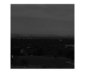
- Stanford when NIR at 903nm
-
 Hazy image
 -
 NIR image at 903nm
 -
 Dehazed image


- Achromatic SanFrancisco when NIR at 903nm
-
 Hazy image
 -
NIR image at 903nm
-
 Dehazed image


A consistent trend in the right most dehazed images above is the clarity and edge sharpening of distant imagery such as mountains and clouds. In the output image of Stanford dish and Stanford for example, there has been a significant improvement in the detail of the distant objects which are the mountains in this case. Also, the clouds which are by definition prone to the maximum amount of haze in landscape images due to the blue colorcast are much clearer in the dehazed output images. Thus the aim to make distant objects appear haze-free in landscape images has been achieved. As mentioned above, the mean square error has been calculated for each of these images by comparing the resultant output dehazed image with the corresponding polarized image after normalization of both the images. The error varies from 0.5% in the achromatic version to 7.32% in the chromatic version.The dehazed image for the San Francisco image at 757 nm is visually not as clear as compared to the dehazed image at 903nm. This could be attributed to the fact that the NIR at 757nm does not encapsulate as much detail as the NIR at 903 nm which is evident from from the corresponding NIR images. The results are tabulated when NIR is at 903nm as follows:
| Landscape Image | Mean Square Error |
|---|---|
| San Francisco Achromatic | 0.5% |
| San Francisco RGB | 2.33% |
| Dish | 2.53% |
| Stanford | 7.32% |
Skin Smoothing
Motivation

As is the motivation of this project in general, the skin smoothing portion is designed to be an automation of a commonly performed post processing technique. In many cases, photographs (specifically portraits) are edited to remove small unwanted characteristics in faces. This can be seen in images of models in ads, actors in movie posters, and professional grade portraits. It is common to "touch up" a photograph by removing small wrinkles, blemishes, and freckles from the skin; often this is done in photoshop by a professional editor or with relatively complex algorithms to attempt to automate the process. It is proposed by Susstrunk and Fredembach that near infrared data can be utilized to more accurately automate this process [1][2][3].
The theory for using infrared is described best by the reflective properties of melanin and hemoglobin -- longer wavelength light reflects less [2]. This means that near infrared light will penetrate further into the skin than that in the visible spectrum. With that in mind, it can be shown that infrared images effectively capture the deep, important structural information of a portrait, while not capturing the shallow, unwanted information. For example, freckles and small wrinkles do not show up in an infrared image, but the edges that define the eyes, mouth, and nose do. Using this as a basis for the theorem, this portion of the project explored possible algorithms to generate smoothed images that maintain all of the structural information intended to be kept in the final portrait.

Methods
In exploring algorithms for skin smoothing, several papers were referenced and read, but the basis of the final algorithms originated from two sources. Each of the algorithms have the same general structure, but have a few distinct differences. Each will be discussed independently, and the results will be shown separately in the next section.
Algorithm 1

The first algorithm stems from the work of Fredembach and Susstrunk [3], in their work on skin smoothing using infrared. The first step in this algorithm is to convert the RGB image to the YCbCr color space. A bilateral filter is then applied to both the luminance channel of the visible spectrum (the Y), and the infrared image. In doing this, the luminance channel blurs the color image, making all edges more gradual and thus all details a bit more smooth. This effectively makes the image a smoothed version of the original. After applying a bilateral filter to the Near Infrared image, the detail layer must be obtained. In this algorithm, the method for defining the detail layer is undefined, but the idea is to keep only the important edges.
Using the equation:
the resulting residual image of the infrared channel contains only the edge details remain as non-neutral values. It is then possible to threshold for large values of the residual image (in both positive and negative values), so that when an edge is known the luminance of the combined image comes from the residual, and when there is no edge the luminance is the blurred version calculated from the filtered color image.
The final luminance is a combined version of the filtered luminance from the RGB image and the residual IR image, and is calculated per pixel as:
The values of gamma and alpha, as well as the thresholds can be changed by the user if necessary.
Now, after the final luminance is calculated, the chrominance information from the color image (the CbCr) is added back into the image, and all is converted back into the RGB color space.
Algorithm 2

The second algorithm is based on the work of Edelmann and Durand [4]. The inspiration for this algorithm came from exploring uses for bilateral filters. The authors were attempting to use two images -- one taken with a flash and one taken without -- to create a combined image that has the structure of a well lit scene with the smooth and warm lighting of a scene lit with ambient light. The idea is that the structure can be taken from the information of a flash image and the color taken from the non-flash image. Similar to the first algorithm, the first step is to convert to YCbCr. A bilateral filter is still applied to the luminance channel of the RGB image, but now two bilateral filters of differing widths are applied to the IR image. A smaller width image (IR_V) will smooth less, and will preserve the details of the edges more precisely, while a wider filter (IR_W) will smooth more broadly. The two filtered results are then divided to provide a ratio, which creates a smoothed luminance channel from the original IR image.
The equation for the pixels in the detail layer in this algorithm looks like:
Once the detail layer is defined, a smooth final luminance can be calculated as the per pixel product of the smoothed YCbCr luminance times the Detail layer:
Now the chrominance information is added back in, and the entire image is converted back into the RGB color space.
Results


In examining the outputs from the different algorithms, it can be concluded that using near infrared as a method of automating skin smoothing does work quite well. In the outputs of the first algorithm, the blemishes and wrinkles exhibited in the original images are smoothed out of the final image. In the zoomed in image, it can be seen that the details fundamental to the structure of the face are still in tact (e.g. the edges around the eyes). What is interesting to point out is that the first algorithm allows for easy manipulation of the amount of smoothing in the final image. By allowing the user access to the width of the bilateral filters as a variable parameter, this can become an easy automatic version of skin smoothing.
The second algorithm, on the other hand, allows for more precise manipulation of the amount of smoothing allowed. Since three bilateral filters are used, each parameter can change the final output quite significantly, and thus would not be as easily used by an average user to automate skin smoothing. This method has the potential to yield the same or better results, but requires more precise manipulation of several variables to get a desired output. By looking at the output images in this section, it can be seen that this does in fact yield results with a bit more detailed images (i.e. the facial hair in the male images).
Overall, the skin smoothing algorithms that utilize near infrared are comparable to those that use just RGB data, and are generally more simple for an average user. They do not require an experienced photoshop user or any significant user input to generate images that remove unwanted features while maintaining all necessary structural features of a face. In the end, there is improvement that can be done on the algorithmic side, but this is proof that the theory is sound.


Conclusion and Future Directions
Future Directions
Future work extending our project could involve experimenting with more post-processing algorithms that may benefit from the use of Near Infrared data. Some suggested areas, which we as a group managed to begin but not complete are Shadow Elimination and Illuminant Detection.
Explored Ideas
Shadow Elimination
Shadow elimination begins with shadow detection. In order to detect regions of shadows in an image, people have used the basic insight that most dark objects in an image are not dark in all 3 channels (R,G,B) while shadows are mostly dark in all three bands. More robustness can be achieved by using ratios (R/NIR, G/NIR, B/NIR) to indicate presence of shadows. Although simple to implement, we realized that any publication on shadow removal would show examples with no dark objects and a well-lit atmosphere. The images we possessed didn't quite satisfy these requirements - they would either have faces (where hair is dark in all bands) or dark trees (the green would always be detected as shadows by these algorithms). We refer the interested reader to [1].
Illuminant Detection - The benefits of being able to detect and correct for the illuminant of a scene are well known, and Süsstrunk and Fredembach have suggested methods for accurately approximating the illuminant in a scene. We explored this algorithm, and attempted to recreate and test it, but did not get past the process of estimating the illuminant temperature in the way they describe. The heuristics they use to make the final illuminant decision require knowledge of their data sets or more images in different lighting environments to fully test. That being said, the potential benefits of this are large, but were not fully explored in this process.
Conclusion
The algorithms and theories explored in this project are proof that near infrared data is useful for post-processing techniques and may allow for automation of computational photography methods. They improve upon the methods currently used, and show that exploration of further uses of NIR in computational photography is worthwhile. Since the setup required to capture NIR is often quite complex, there needs to be a wider gamut of applications than just those discussed here for NIR capture to become a standard feature in digital cameras.
Acknowledgements
We would like to thank Dr.Joyce Farrell, Dr.Torbjorn Skauli and Dr.Hagit Hel-Or for providing us with copious hyperspectral data and also for their help throughout the project. We also appreciate the feedback from Prof.Brian Wandell and Henryk Blasinski that helped us refine our project thought process.
References
[1] Süsstrunk, Fredembach. "Enhancing the Visible with the Invisible: Exploiting Near- Infrared to Advance Computational Photography and Computer Vision." SID International Symposium Digest. School of Computer and Communication Sciences, EPFL, Lausanne, Switzerland. 2010.
[2] Süsstrunk, Fredembach, and Tamburrino. "Automatic Skin Enhancement with Visible and Near-Infrared Image Fusion." School of Computer and Communication Sciences, EPFL, Lausanne, Switzerland.
[3] Fredembach, Barbuscia, and Süsstrunk. "Combining visible and near-infrared images for realistic skin smoothing." School of Computer and Communication Sciences, EPFL, Lausanne, Switzerland.
[4] Eisemann, Durand. "Flash Photography Enhancement via Intrinsic Relighting." Massachusetts Institute of Technology.
[5] Lee et al. "An Algorithm For Automatic Skin Smoothing in Digital Portraits." Electrical and Computer Engineering, Purdue University. 2009.
[6] Schaul, Fredembach, and Süsstrunk. "Color Image Dehazing using the Near-Infrared." School of Computer and Communication Sciences, EPFL, Lausanne, Switzerland.
[7] http://en.wikipedia.org/wiki/Photodiode
[8] X. P. Zhang, T. Sim, X.P. Miao, "Enhancing Photographs with Near Infrared Images", IEEE Computer Society Conference on Computer Vision and Pattern Recognition 2008, Ankorage, US.
[9] S. J. Zhuo, X. P. Zhang, T. Sim, X.P. Miao, "Enhancing Low Light Images Using Near Infrared Flash Images", IEEE Conference on Image Processing (ICIP), 2010
[10] Z. Farbman, R. Fattal, D.Lischinski, R.Szeliski, "Edge preserving Decompositions for multi-scale Tone and Detail Manipulation." The Hebrew University.
Appendix I - Presentation slides and Matlab code
Matlab code
Presentation Slides
File:NIR project presentation.pdf
Appendix II
The work was split evenly between all three members of the group, each working on an individual section and assisting the other group members as necessary.
Sabarish Sankaranarayanan - Contrast Improvement, explored Shadow Elimination
Serene Kosaraju - Haze Removal in Landscape images
Evan Lee - Skin Smoothing, explored Illuminant Detection