NarasimhanShankar

Back to Psych 221 Projects 2013
Background
The goal of this project was to build an inexpensive photo-spectrometer and compare its performance to the expensive PRS650 in the VISTA lab. The parts chosen for the design are simple off-the-shelf components that are available at any office supply store. While expensive lab-grade spectrometers are used for research purposes including astronomy, gas analysis and crystallography, the inexpensive spectrometer will be used by amateur users for purposes like brewing, checking the fat content in milk and examining soil samples. The inexpensive photospectrometer described below costs less than $10. Components were obtained and an apparatus was designed to focus light on the diffraction grating. The picture of the diffracted pattern was taken with the help of a phone camera and the Spectral workbench software on the publiclab.org website was used to analyze the data.
Optics
Light which has wave-like properties is composed of various colors. A spectrometer is a device that splits light into the various colors it is composed of, which we otherwise cannot distinguish with the naked eye. By viewing a substance through a spectrometer, one can distinguish the exact mixture of colors, which correspond to specific wavelengths of light. These can be compared to other spectra to help identify the sample. The types of spectroscopy depend on the spectrums being examined:

Continuous Spectrum
Absorption Spectrum
Emission Spectrum
Apparatus Design
For the purposes of comparison, two designs were built that made use of different diffraction mechanisms:
1) Black Box Design
This design made use of transmissive diffraction. A DVD was used for the diffraction grating. The stickers and silver coating on the DVD were removed to provide a transparent surface for the propagation of the light. Black cardboard was used to make the enclosure. The dimensions of the enclosure are 2 in. x 2 in. x 12 in. On one side of the cardboard box, razor blades were used to make the slit. Razor blades provide a sharp and stable edge that is needed to focus the incoming light. On the other side, the DVD (now transparent) is cut so that the diffraction array appears perpendicular to the slit. The camera will be mounted on the side of the diffraction grating to capture the image of the diffraction pattern.

2) Cereal Box Design
This design made use of reflective diffraction pattern. Light is incident on the DVD diffraction pattern and is reflected off the silvered side of the DVD. The DVD is angled at 60 to the plane of the incoming light. The light hits the diffraction pattern and is reflected off the silvered side of the DVD. The reflected image is captured and is uploaded on spectralworkbench to examine the spectrum.

Experimental Method
In order to compare the workings of the simple spectrometer and the PR650 available in lab we pursued two methods of data collection. The setup involved obtaining data from two different light sources and also measuring the same with different color filters.
Here are a few pictures of the setup in lab. The first image shows the PR650 measuring light from the monitor. The second picture shows the inexpensive device measuring light from the incandescent light source with a red color filter.


The color filters used in the experiment were:
- Red
- Yellow
- Green
- Blue
The two spectrometer designs were tested with both light sources. From our initial experiments we noticed that the incandescent source was too bright for the PRS650 to measure directly and while the computer screen even with a white background was not bright enough for the inexpensive device to provide a good spectrum (bright enough to be captured by the camera).
Therefore we also obtained results for the PRS650 and the incandescent light source by focusing on reflected light. The incandescent source was pointed towards a white reflective surface and the resulting light was indirectly captured by the PRS650. The picture below shows the setup for this test.

The reflected light from the incandescent light source also did not pose as an ideal source for the PRS650. The spectrometer detected large amounts of IR which had the effect of washing out other data from the visible spectrum. This was corrected for in post processing where the IR was digitally filtered out using MATLAB. The resulting PRS650 spectrum provided a good comparison for the inexpensive device.
Results
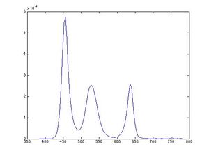
The PRS650 was first used to measure the spectrum emitted by the computer monitor. The monitor consists of red, blue and green colors. A blue colored filter was used to as a single pass filter to filter out all components of the light except the blue color. The spectrum obtained shows the intensity as a function of wavelength. A peak is seen in the visible range of the blue color.

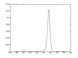
Next, the same experiment is performed with a red colored filter and a peak is observed around the wavelength for red light.

One fact to note is the significantly better coupling of the central LED than the perimeter LEDs. This is largely due to the limitations of the Luxeon initial lens assembly - the so-called "circular region" they detail as the "beam neck" is actually a number of overlapping circular focal points. This causes imperfect coupling of the perimeter LEDs into the fiber.
One of the interesting side-effects of our fiber coupling design is that the light output from the fiber, before being diffused, takes up different patterns depending on which LED is on. For instance, the central LED will result in a circular region being illuminated in the center of the fiber output.


On the other hand, any of the perimeter LEDs will result in a ring shaped illumination region. This is largely due to different fiber coupling of those LEDs in contrast to the central LED.


Conclusions
In the end, we produced a fiber-coupled LED source that we believe addresses the design criteria. We found that 3D printing the enclosure and opting for adjustable focus allowed us to compensate for the unpredictable performance of the luxeon lens assembly without resorting to redesign.
Further refinement of the design should allow for better coupling of the perimeter LEDs into the fiber. The central LED couples successfully, but we feel that there is definite room for improvement (probably through different optics than the Luxeon assembly for the first lens), that will enable better performance. In the meantime, it seems that a reasonable amount of power enters the fiber from any of the LEDs used.
Here is a video. The LEDs are controlled with an Arduino at about 30mA of current. File:Illuminator.zip
HyperPhysics Diffraction Grating
Absorption and Emission Spectroscopy
Appendix I - Data
Appendix II - Work partition (if a group project)
Mechanical Design of the apparatus - Gautam Narasimhan
Diffraction grating design + Part Sourcing - Ashwin Shankar
Testing / Evaluation - Gautam Narasimhan
Documentation - Ashwin Shankar
