SharmaRavichandran
Active LED based Illumination control
Motivation
Illumination control of LEDs dominantly uses Pulse Width Modulation using a Microcontroller. The major drawback of this method is the discreteness of the illumination, i.e. the LEDs are continuously toggled. This creates high frequency flicker and is disturbing in situations that demand high temporal resolution. The goal of this work is to prototype a device that controls the LED intensities more directly, rather than switching it on/off.
Device Specifications
An ideal device should
- Control the LED intensities directly without toggling.
- Provide a Linear response between LED illumination and Control variable
- Support multiple channels or easily be duplicable, often to control multiple colour LEDs together or separately.
- Utilise the entire intensity range of the LED and provide high dynamic range
- Provide options to be compact and portable.
Circuit
-
 Designed Circuit

Components
- LED Array
- Luxeon's Predefined 7 LED Round Assembly SR-02-00015
- Arduino Uno (microcontroller board)
- Heat Sink 2.25 Inch diameter
- Two 9 Volt Batteries
- We used Energizer Procell
- PCB,Breadboard and interconnects
- Circuit Components
Design Methods
LED array
Requirement
We require high intensity LEDs with well defined Spectral properties. The LEDs must provide high dynamic range and must be suitable to operate in portable conditions with limited current. Multiple LEDs are required in different colours to help in various vision experiments. Each LED must have its own channel to be controlled independently.
Methods
A Light Emitting Diode is a Current Controlled Device. The intensity of the LED is defined by the current flowing through it. So, controlling the LED intensity is equivalent to controlling the current through the LED. This work uses a Luxeon LED Array that has 7 high intensity LEDs in different colours. These colours are chosen such that the effective spectrum of the array covers the entire visible spectrum. This array can be operated to use the LEDs independently or serially. Each LED is rated at 700mA-1A maximum currents, and operates at a 20mA minimum current as well.
Microcontroller and Control Variable
Requirement
This project requires a control of illumination using an Arduino Microcontroller. Typically, it’s required that the microcontroller provide a voltage/current output, which can be used to control the illumination of LEDs.
Methods
Arduino Microcontroller, a digital device, can provide feeble currents up to 40mA, which is unsuitable to drive a high power LED. So, we must use the voltage output as a control variable. But, a microcontroller’s analog output is a Pulse Width modulated digital signal, and using this would defeat the whole purpose.So, the digital output of the microcontroller must be interfaced to control the analog components that follow. Hence, a digital potentiometer is used to provide an analog output voltage. This digital pot would be serially interfaced with the Arduino microcontroller and the control variable is the potentiometer level that decides the output voltage, which is a controlled fraction of the total voltage at one end of the potentiometer.Conclusively, the digital pot level is the control variable. This can be controlled on an Arduino's computer interface. A sophisticated firmware can be written to enable internet control of these levels, which was implemented in this work as well. Appendix contains the firmware and the details of the internet control implementation.
Digital Potentiometer
Requirement
A digital potentiometer is a device whose resistance ratio is controlled by the microcontroller. A digital pot is characterized by its total resistance, and the resolution of the resistance ratio. This resolution is the ratio of the total resistance and the total number of levels (steps) that the device can be operated on. This level is chosen through the Microcontroller and serially transmitted through I2C Protocol.
Methods
The digital potentiometer used in this work is MCP4151 and this uses a 10K total resistance and 256 steps/ levels. The Microcontroller transmits one of the 256 levels (0-255) and the resistance ratio () is controlled. This ratio also signifies the fraction of the voltage supplied to the total resistance. This voltage fraction is the analog output that can be used to control the next stage.Total resistance is insignificant to us, as the voltage fraction is more important to us. However, the total resistance must be large enough to reduce static power dissipation from the voltage supplied. The resolution of the potentiometer is significant as this decides the resolution of the output voltage. Better resolution provides smoother output voltage range.A limitation of most digital potentiometers is the limit on the voltage supplied to the total resistance (mostly 0-5V). This limits the voltage output of the pot.
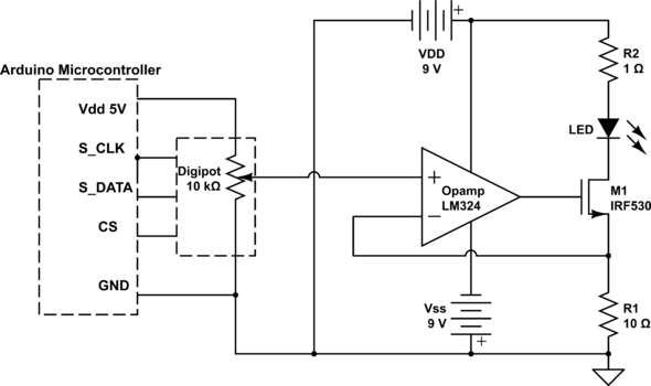
The Arduino controller communicates serially with the Digital Potentiometer. It uses a I2C interface, where S_Clk denotes the Serial clock and S_Data denotes the Serial Data. The Pin CS denotes the Chip select. Various resources and tutorials are available online to implement I2C communication using Arduino controllers, or any controller.
Voltage controlled Current Source (VCCS)
Requirement
A voltage controlled current source that drives a controllable current through the LED. The voltage will be provided by the digital potentiometer must be converted into suitable current that drives the LED.
Methods
This can be implemented using any famous VCCS active device such as a MOSFET or a BJT. These provide, respectively, quadratic and exponential voltage to current functions. That is, the current grows faster than the control voltage. Hence, it’s not possible to achieve desired linear intensity response with these devices.After exploring several options, a circuit was designed to provide a voltage follower response. This involved using an operational amplifier, a MOSFET and a couple of resistors. This implements a voltage follower circuit, where the current through the MOSFET follows the voltage input to the op-amp.
Final Design
Operation
The circuit takes in the voltage from the potentiometer as the input and provides a current that is a linear function of the input voltage. The input voltage is given to op-amp’s non-inverting terminal (3) and the output terminal (1) drives the gate (G) of the MOSFET. The MOSFET obviously produces a quadratic current response. The LED is connected in the current loop of the MOSFET, either in the drain or the source. The resistor R1 in the MOSFET source acts as a feedback element, and the voltage across R1 is fed back to the op-amp’s inverting terminal (2). This acts as a feedback and this makes the response linear. The slope of this linear response can be is the resistance R1 directly. This is a Voltage Follower characteristic.
Linear Response
Eventually, the Output current through the LED is , where Vin is the input voltage to the op-amp. The resistance R2 in the current loop of the MOSFET limits the maximum current that can flow in the loop and saves the LED from very high currents.
So, the LED current is linearly proportional to the Digital Pot level that is controlled on Arduino microcontroller, with R1 deciding the slope of the linearity.
Operational Amplifier
An op-amp is a differential amplifier which is a basic comparator when used without a feedback, and as an amplifier with a feedback. An ideal op-amp has an infinite differential gain and hence tries to establish a short between the input terminals. This is exploited in this design. An When an input voltage is given to one of those input terminals and if the other terminal feeds back from the output, in this case, and tried to make
Thereby a linear V-I characteristics is observed. And, as the LEDs intensity is a linear function of its current. the linearity is preserved. A significant non-ideality of the mosfet is the non-infinite gain and thereby a significant input offset voltage between the input terminals. this leads to a dark voltage at the output and thereby a dark-current through the LED. This limitation is mitigated by providing a negative voltage supply to the op-amp's VSS terminal, instead of simply grounding it. This trivializes the offset voltage bringing it very close to zero.
MOSFET
A N-channel MOSFET is used in the design to convert the op-amp's output voltage to LED current. Op-amp provides a Voltage sampled voltage feedback around the MOS. This transistor must be chosen to have a low threshold voltage to support low currents and not limit the performance, and must be capable of withstanding up to 1 A current.So, this project uses a IRF530 Power NMOS that meets all the requirements.
Feedback Resistance R1
This is the very crucial element of the design, and it defines the slope of the transfer function as described earlier. This is typically around 10 , so as to get 500mA maximum current with 5V input, with a modest supply to op-amp and MOSFET. This can be changed as per need. This work concentrates on establishing the linearity and illumination control. So, the circuit uses a 10 resistor. Although it is possible to reach better currents by decreasing R1, it is important to understand that, as R1 decreases, the slope increases, and it will not be practical to meet lower current values, rather lower LED intensities at a given voltage resolution.. But, this can be overcome by increasing the output Voltage range of the pot, from 5V. Unfortunately most digital pots do not support higher voltages.
Current Limiting Resistance R2
Another resistor is essential in the design to limit the current flowing through the LEDs, for all practical purposes. This current limiting resistor is chosen so as the limiting current is below the maximum current rating of the LED. This resistance is chosen as 1 in the practical design. For instance, the limiting currents are around 550mA and 400mA for Voltage Supplies 12V and 9V respectively. This is far below the rating of the LEDs which is around 700mA.
Voltage Supplies
Voltage supplies at best trade off portability and practicality with accuracy and dynamic range. In this work, four voltage supplies are needed ideally. First supply is at the Digital pot to provide . As the digital pot cannot support voltages greater than 5V, this can be provided from the Arduino board. As the Total resistance of the digital pot is 10K , the Current that is required is 0.5mA, which is way lower than the maximum current that the Arduino can supply. As the total resistance has no impact on the circuit, any available digital pot would meet the current limit.
Secondly, there's a voltage supply to the op-amp's positive supply . As the minimum voltage supply is around 8V for LM324 or any similar op-amps, it's required to use at least a 9V battery or a bulky 12V voltage supply. As the op-amp will not consume a lot of current, a battery might be practically possible.Also, it's important to remember that the op-amp's output voltage can be no larger than the positive supply voltage and no smaller than the negative supply voltage.
Third supply is the negative voltage to the op-amp's negative terminal. Although it works perfectly with grounding the negative terminal, to eliminate the dark current, it is certainly necessary to use a negative supply so as to zero down the offset, as discussed earlier. This voltage is chosen by run and trial as there is a substantial mismatch among op-amps even in a same wafer. A good thing is that the negative voltage can be lower than what is required to bring it to zero, so, for all practical purposes, a -9V will suffice. There are a lot of ways to generate a negative voltage. Either use a laboratory bulky voltage supply, or use a simple 9V battery, with it's positive terminal grounded and negative terminal connected to the op-amp's negative voltage pin.
Finally, there is the voltage supply to the MOSFET. This is important as it determines the maximum current into the MOSFET. So, it's important to check the voltage and current specifications of a supply. This voltage and resistor R2 work together to limit the current. Larger Voltage provides larger current for a given circuit. So, a 12V might provide better currents than a 9V battery. But, to make the circuit portable, this work uses a 9V battery here as well. This is the same as the op-amp's positive supply and they now share the same battery.
Results
Simulation
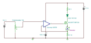
The design was simulated using Texas instruments' TINA-TI. The simulation replaced the digital potentiometer with a voltage generator with a rheostat that gives out a voltage ramp from 0-5 V similar to the digital potentiometer with ramping pot levels. This is expected to induce a transient current response in the MOSFET's current loop. Note the linear transfer function in the plot between the Output LED Current Vs Input Voltage. The design was simulated with a diode replacing the LED. Attempts were made to clone the characteristics of the LED, but the voltage drop across high power LED is very high compared to a normal diode. This may lead to premature saturation in real LEDs.
- Simulation Schematic
-
 Linear Transfer Function

- Simulation Plots
-
 Transient Responses of Input voltage and Output Current
 -
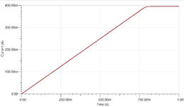 Transient Response of the LED Current
 -
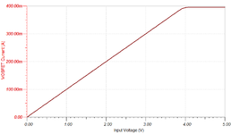 Linear Transfer Function


Initial testing
The circuit was set up on a breadboard and an ammeter was used to replace the LED for sanity check. The response was linear except for the deviations in estimates and that was due to the removal of a diode (LED) as it would have had a voltage drop across it. All the initial testing procedures were performed with a 12V dual power supply. Then the LED was used to observe the illumination response to the voltage levels input from the Arduino. Then, to provide portability and to make the circuit compact, two 9V batteries were used to power up the design.
-
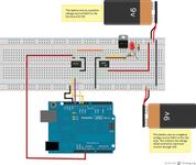 Breadboard connections for the design

Final Results
The circuit was built on printed circuit board and LEDs were connected and spectral responses were observed using a spectrometer. The spectrometer provides the intensity of the LEDs at wavelengths 380nm to 780nm with a sampling interval of 2nm. The LEDs provided very narrow spectrum, as they were monochromatic, and the peak intensities were observed at various pot levels on Arduino (i.e at various input voltages). The pot levels were increased by 20 steps for every measurement. Note the linearity of the device. The illumination saturates after a certain point because the current is limited at that input voltage by the current limiting resistor. This saturation point can easily be moved around by varying the resistor R2, and the current range can be extended by increasing the Voltage Supply . The plots for the green LED are displayed below. Plots corresponding to other LEDs are attached in Appendix I.
- Design Performance (Green LED)
-
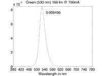 Spectral Response at a certain input level (Control Level = 200, Control Voltage = 3.92V)
 -
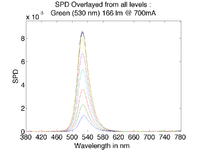 Overlap of Spectral responses over various input levels


-
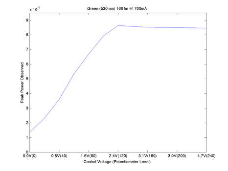 Plot of Peak intensities over various input levels. Note the Linearity

Note that the saturation of illumination occurs sooner than the simulated results. This can be attributed to higher forward voltage drop across the LED than a simulated diode. This could have overcome by decreasing resistance R2 slightly. R2 is already 1. Obtaining a high power resistor with a sub-1 resistance couldn't be done on time. Of course, a parallel 1 with R2 would have halved it, but the current limit would have doubled. Interestingly, this can be easily improved with a higher voltage supply rather than a 9V battery supply. The prototype was initially designed for laboratory use with a power supply for practicality, as batteries don't last long with such current consumptions.
Conclusion
The design successfully establishes a linear illumination control. This can be adapted to control any current driven element. The linear response is very flexible and can be altered, just by controlling a couple of resistances R1 and R2. There are various opportunities of improvement in the design, such as duplicating it to support all seven LEDs in the LED array and controlling all LEDs using a single Microcontroller, independently or together. Thus, the design successfully meets all the device specifications.
Appendix I
Arduino Code
This zipped file has two versions of the Arduino code.
If you want to use it with server/internet control then load the arduino_codeWebControl file to your Arduino.
File:SharmaRavichandran ArduinoCode.zip
Plots
Spectral Responses of LED at various input voltage Levels
Royal Blue(447.5nm) (File:Spd royal blue.zip)
Blue (470nm) (File:Spd blue.zip)
Cyan (505nm) (File:Spd cyan.zip)
Green (530nm) (File:Spd green.zip)
Amber (591nm) (File:Spd dark orange.zip)
Red (627nm) (File:Spd red.zip)
Deep Red (655nm) (File:Spd dark red.zip)
Overlap of Spectral Responses over various input levels
All LEDs File:Overlap.zip
Linear Response
All LEDs File:Linearity.zip
Internet Control
We used popular open source web technologies to achieve the internet control.

NodeJs with following modules:
- Socket.io (for listening to server connections)
- Duino (Arduino interface over virtual Serial port (USB) ) Duino on github
XAMMP or WAMP - basically start a server
YAWCam for webcam streaming
Client Side JQuery based webpage
Check Appendix III for more details.
Appendix II
Work Split up
Arduino and Digital Potentiometer Control : Abhishek
Analog Circuit Design : Karthik
Soldering: Equal split-up
Spectrophotometer measurements: Equal split-up
Internet Control - Programming and Wiki Documentation/Installer etc.: Abhishek
General Wiki Text: Karthik
Internet Control Installation
In order to make things simple for the person interested in using our internet control code, I have created an installer batch file. This batch file installs our web app on your computer so that it can control an Arduino board connected to the LED module over the internet.
For any kind of installation related or actual app related queries contact Abhishek (abhisheksharma AT stanford)
Since, Internet Control is a peripheral part of the project and is not directly relevant to Psych221 I am not providing any nodeJS or server technology documentation on this page. If you need any of those or have questions about the web app, please contact me via email.
Download the file below:
Unzip the LEDfiles.zip to your Desktop (unzipping to other directories will cause the installer script to fail) such that the folder contains the folder called 'files' and 5 other files. Some unzippers may create a nested folder LEDfiles/LEDfiles so make sure that's not the case
Prerequisites:
Installer batch script works 'off the shelf' only if:
- You have a Windows computer
- Unzipped the contents of the zipped folder to Desktop\LEDfiles
- You have installed Wamp to C:\wamp (default) (64 bit Windows installer for wamp available in the zipped files 'files' folder)
- If you have Xammp, you will have to dig in to my installer script and App script to change the folder path to your Xampp path
- You should have installed Visual Studio 2010 Express (available online) and updated
- Install Python 2.7 (installer available in the zipped file) to C:\Python27
- Install Yawcam (installer available in the zipped file) - Yawcam is for realtime webcam streaming.
The installer script now gracefully takes care of the other stuff. (Be sure to be connected to the internet while running the installer script, it gets files off the internet)
Run the installerLED.bat file (this is the installer script). This does a bunch of stuff to install Nodejs and the relevant modules. It also copies the HTML, JS code to C:\wamp\www\ledControl
Now run the wamp server if it's not running already.
Now when all this is done, you can connect the Arduino (already loaded with the Arduino code) and execute the file startAppLED.bat
This will start the server and allow the arduino to control the LED via the internet.
To test go to localhost from your web browser, it will load up the control webpage